Dear Toradex Support Team,
I hope this message finds you well. I am currently facing an issue related to GPIO state instability on my imx8 mini SoM and torizonCore 6, and I would appreciate your assistance in resolving this matter. Below, I have outlined the details of the problem:
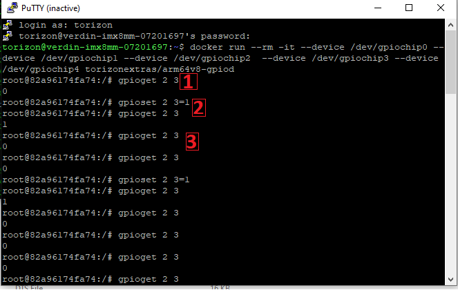
As you can see from the image below after modifying the DT when I read the SODIMM 21 it shows 0 and if I set it to 1, I connect to LED and it turns on the LED again, and if I read again the pin it changes to zero, and the led changes to zero.
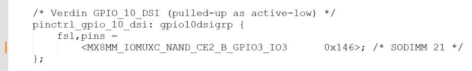
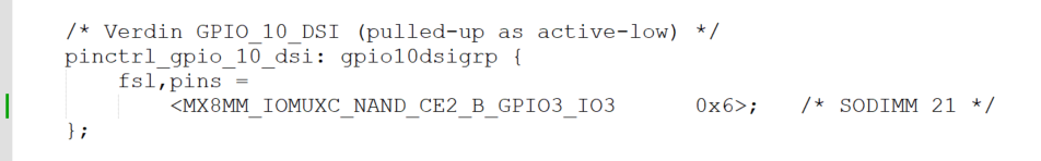
I was wondering how should I set up the register values for the hexadecimal number that represents a normal GPIO output pin, once I put 0x146 all the time the response was 1 and then I tried 0x6 but it is not stable when I read twice.
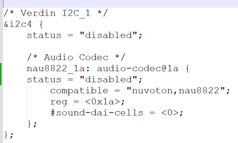
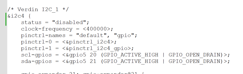
I disabled the I2C_1 and added the overlays on yaml file.
tcbuild.yaml (4.9 KB)
torizon@verdin-imx8mm-07201697:~$ sudo ostree admin status
Password:
* torizon efa690fc308818d8c537803b9856d30faada2684837498236539d55b70065b09.0
    Version: 6.2.0+build.2-tcbuilder.20231024145434
    origin refspec: tcbuilder:efa690fc308818d8c537803b9856d30faada26848374982365                                                                                                                                                             39d55b70065b09
  torizon 93a34a335768b487f66007ebf9ce230101de3b6be8cf4cdabe3d776e8c3be69a.0 (ro                                                                                                                                                             llback)
    Version: 6.2.0+build.2-tcbuilder.20231024144124
    origin refspec: tcbuilder:93a34a335768b487f66007ebf9ce230101de3b6be8cf4cdabe                                                                                                                                                             3d776e8c3be69a
Thank you for your attention to this matter. I appreciate your support in resolving this issue, and I look forward to your guidance.
Best regards,
Mehrdad