I have a custom TFT Display (TCG070WVLSJPPA-GD20) which I setup with the Colibri Evaluation board using a Colibri imx8x chip.
I was able to get the touch and display to work however I am seeing some artifacts and flickering on the screen.
Kernel version: toradex_5.15-2.1.x-imx
Device Tree Settings
&panel_dpi {
     // Enable //
    status = "okay";
    compatible = "panel-dpi";
     /* for 0.3mm pixels */
    width-mm = <152>;
    height-mm = <91>;
     // Timing //
    panel-timing {
        clock-frequency = <33200000>;
        hactive = <800>;
        vactive = <480>;
        hsync-len = <96>;
        hfront-porch = <16>;
        hback-porch = <48>;
        vsync-len = <2>;
        vfront-porch = <10>;
        vback-porch = <33>;
        pixelclk-active = <0>;
    };
};
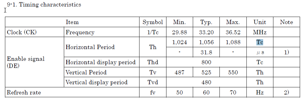
Timing Characteristics
Video
You can use our share server to upload your video.
Sorry but I can’t see any artifacts in the shared video. Could you please explain what exactly is wrong with the displayed image?
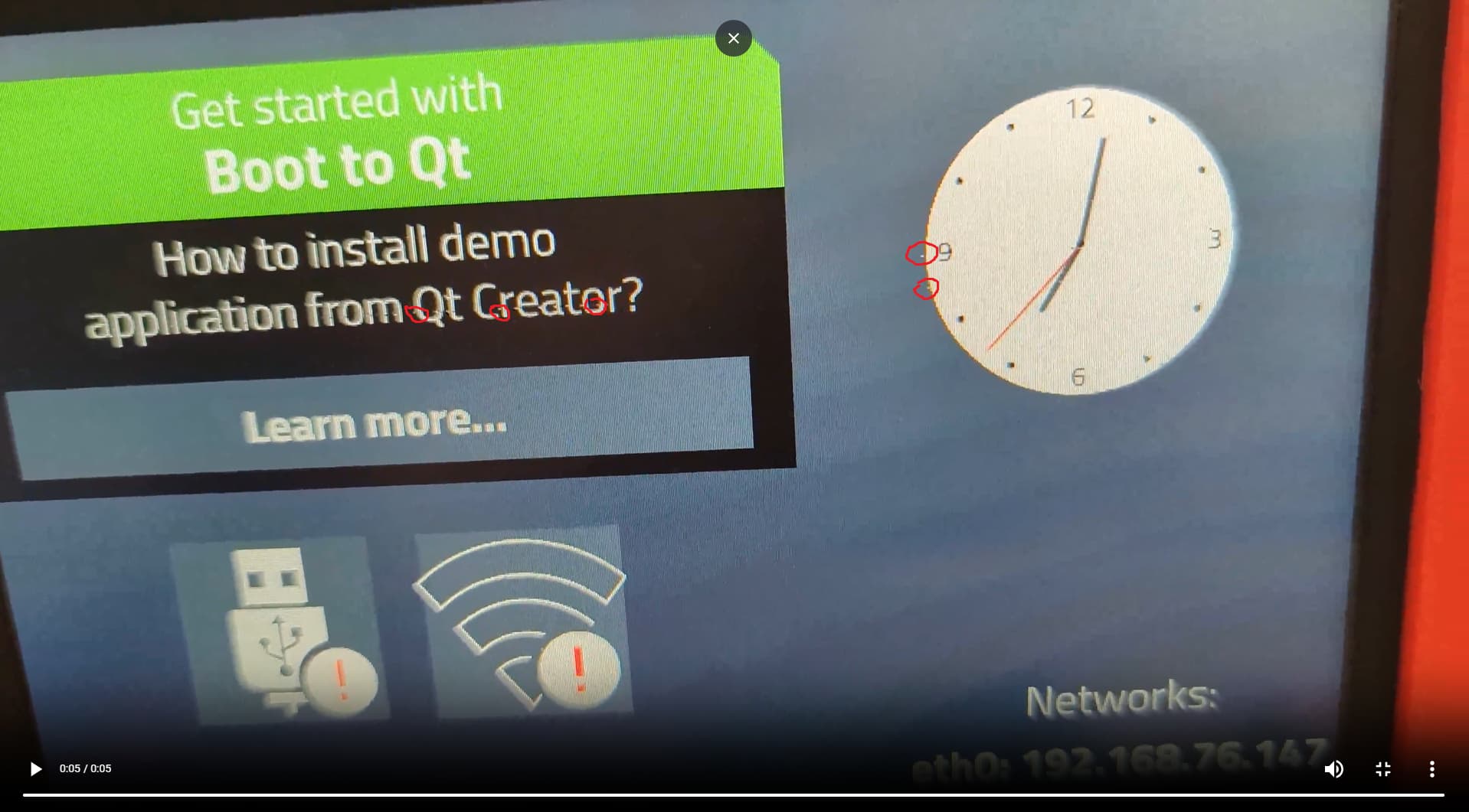
If you focus on the clock area you will see white spots appear.
Sorry, I’ve run your video more than 10 times, but I still wasn’t able to see any artifacts.
Please see an attached image with the artifacts circled in red.
If you play the video you will see these white artifacts appear.
I also posted the uncompressed version of the video where the artifacts are much more apparent.
https://share.toradex.com/z8mkxbx3zvfyrgn
It appears to be a signal integrity issue. How exactly is this display connected to the Colibri Evaluation board? Are you using any kind of adapter? What is the length of the cable?
I have a breakout board which interfaces with the X20 (Generic RGB Display) header on the Colibri Evaluation Board.
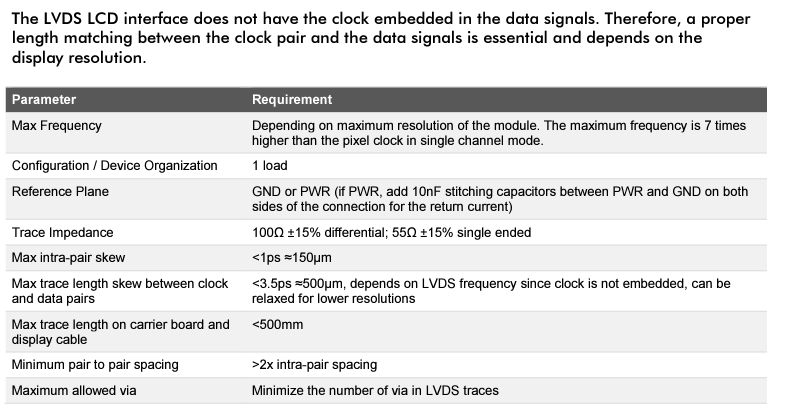
On the Breakout board I have a LVDS Transmitter compatible with my display (SN65LVDS93). The RGB traces from the X20 connector run into it and the LVDS output runs into the display.
Please double check your breakout board design and layout. The signal integrity issue can be caused by a number of factors such as reflections, crosstalk, electromagnetic interference (EMI), power supply noise, or even termination mismatch. Signal integrity can be significantly affected by the layout of your PCB. Try to keep differential pairs tightly coupled with the same length to avoid timing skew. Also, keep the signal paths as short as possible, and avoid abrupt changes in direction which can create signal reflections. Please also note -