Flickering 7" TFT

Hello,

We are developing a new project that needs a 7" screen. (For other applications we are using a 5" screen and works well). Its a 24bits interface.

We are using a custom carrier board with Colibri IMX7 and we can see some Flickering on the graphs of the 7" sreen (in the 5" we can not see this malfunction).

Here a screen shot of the custom carrier schematic:

I read something about if you need to change from 5" to 7" you need to switch the Clock signal. This is the datasheet of the 7" screen:

I have measured with the osciloscope the clock and HSYNC and I see that HSYNC takes some value between 1 and 0. Here a screen shots of the occiloscope:

The blue signal is CLOCK the yellow signal is HSYNC.

Is this kind of behavior normal?

Thanks.

Juan Carlos

Dear @jmartinez,

Welcome to our community. Please feel free to roam around and ask for support anytime needed.

About your issues, I’d like to confirm some information with you:

  1. Which Image and which version are you using?
  2. Have you made any custom change to that image, such as editing kernel configuration?
  3. Which Version of the module are you using?
  4. Have you set your own custom overlays? Would you be able to share the custom properties that you set to your display and also maybe the full datasheets so that we could check if there is something missing? We found two datasheets that seem to be the ones you’re using but we’d like to confirm it.
  5. Finally, do you experience it on any application, or is there a specific use case where this happens? Can you please share on a photo of what you see on the screen?

Best regards,
Guilherme

hello!!

The image we are using is a custom one, based on yocto thud.

Yes, we have changed some drivers, device tree, etc. in order to make our old 5" TFT display work, like many other devices.

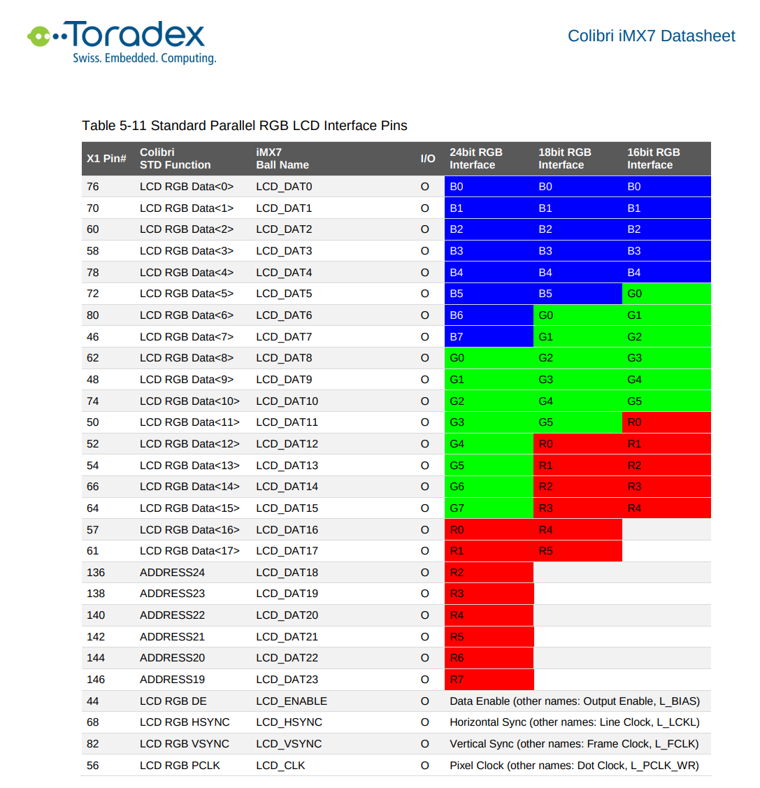
The SOM we are using is a Colibri IMX7D 1GB V1.1A.

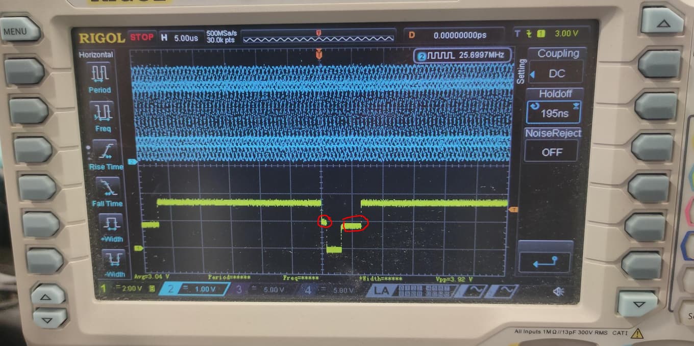
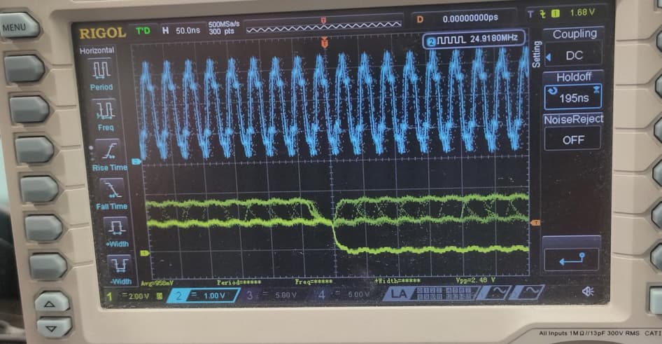
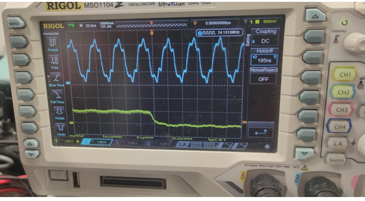
The problem that we have is that some pixels fliker, so for example, white letters on a black background produce noise and there is a cloud of white pixels filering around the letters.

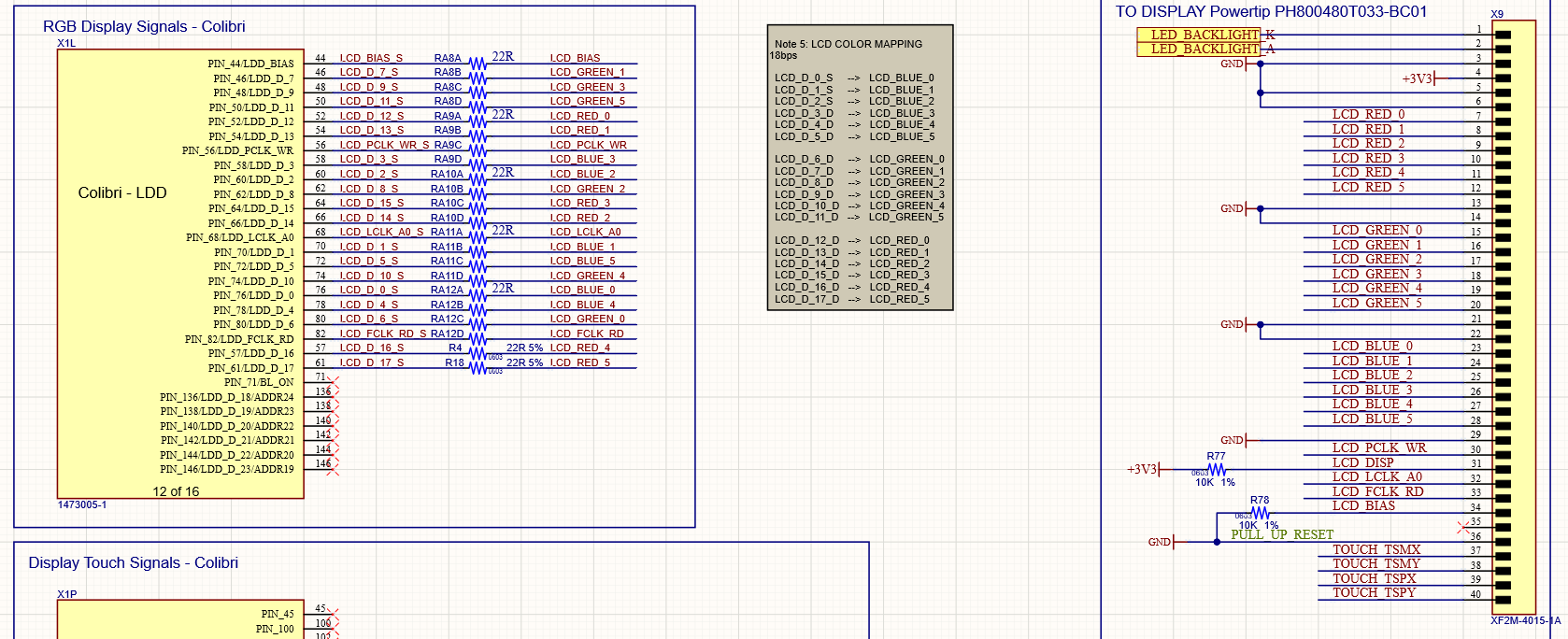
Our device tree patch for the LCD

imx7-colibri-viola.dtsi

+&lcdif {
+    display = <&display0>;
+    status = "okay";
+
+    display0: lcd-display {
+        bits-per-pixel = <16>;
+        bus-width = <18>;
+
+        display-timings {
+            native-mode = <&timing_wvga5>;
+
+            /* Standard VGA timing */
+            timing_vga: 640x480 {
+                clock-frequency = <25175000>;
+                hactive = <640>;
+                vactive = <480>;
+                hback-porch = <40>;
+                hfront-porch = <24>;
+                vback-porch = <32>;
+                vfront-porch = <11>;
+                hsync-len = <96>;
+                vsync-len = <2>;
+
+                de-active = <1>;
+                hsync-active = <0>;
+                vsync-active = <0>;
+                pixelclk-active = <0>;
+            };
+
+            /* WVGA Timing, PH800480T024-IBC01 */
+            timing_wvga5: 800x480-5 {
+                clock-frequency = <33300000>;
+                hactive = <800>;
+                hback-porch = <46>;
+                hfront-porch = <210>;
+                vactive = <480>;
+                vback-porch = <23>;
+                vfront-porch = <22>;
+                hsync-len = <20>;
+                vsync-len = <20>;
+
+                de-active = <1>;
+                hsync-active = <0>;
+                vsync-active = <0>;
+                pixelclk-active = <0>;
+            };
+            
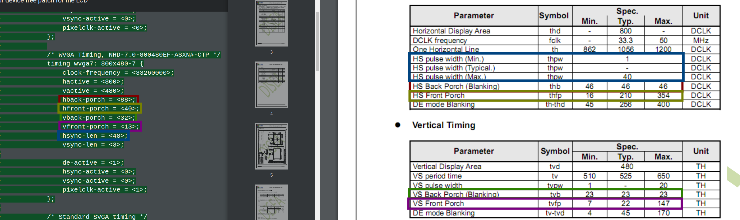
+            /* WVGA Timing, NHD-7.0-800480EF-ASXN#-CTP */
+            timing_wvga7: 800x480-7 {
+                clock-frequency = <33260000>;
+                hactive = <800>;
+                vactive = <480>;
+                hback-porch = <88>;
+                hfront-porch = <40>;
+                vback-porch = <32>;
+                vfront-porch = <13>;
+                hsync-len = <48>;
+                vsync-len = <3>;
+
+                de-active = <1>;
+                hsync-active = <0>;
+                vsync-active = <0>;
+                pixelclk-active = <1>;
+            };
+
+            /* Standard SVGA timing */
+            timing_svga: 800x600 {
+                clock-frequency = <40000000>;
+                hactive = <800>;
+                vactive = <600>;
+                hback-porch = <88>;
+                hfront-porch = <40>;
+                vback-porch = <23>;
+                vfront-porch = <1>;
+                hsync-len = <128>;
+                vsync-len = <4>;
+
+                de-active = <1>;
+                hsync-active = <1>;
+                vsync-active = <1>;
+                pixelclk-active = <0>;
+            };
+
+            /* Standard XGA timing */
+            timing_xga: 1024x768 {
+                clock-frequency = <65000000>;
+                hactive = <1024>;
+                vactive = <768>;
+                hback-porch = <160>;
+                hfront-porch = <24>;
+                vback-porch = <29>;
+                vfront-porch = <3>;
+                hsync-len = <136>;
+                vsync-len = <6>;
+
+                de-active = <1>;
+                hsync-active = <0>;
+                vsync-active = <0>;
+                pixelclk-active = <0>;
+            };
+        };
+    };
+};

Changes in the mxc_lcdif.c driver:

drivers/video/fbdev/mxc/mxc_lcdif.c
@@ -37,6 +37,18 @@ struct mxc_lcdif_data {
 
 static struct fb_videomode lcdif_modedb[] = {
     {
+    /* 800x480 @ 60 Hz , pixel clk @ 33.26MHz */
+    "NHD-7", 60, 800, 480, 30066,
+     .left_margin = 88,
+     .right_margin = 40,
+     .hsync_len = 128,
+     .upper_margin = 32,
+     .lower_margin = 13,
+     .vsync_len = 45,
+     .sync = FB_SYNC_CLK_LAT_FALL,
+     .vmode = FB_VMODE_NONINTERLACED,
+     .flag = 0,},
+    {

Here a video with the problem (look at lettes “e” and “a”:

Here the datasheet:

ZW-T070SWH-40CP Spec-3.pdf (1.6 MB)

Regards.

Juan Carlos

Dear @jmartinez,

Thank you very much for the update. I have a few questions for you in order to solve your issue:

Did you use our BSP 3 to make this custom image or did you come up with something from zero?


Looking at the patch and the datasheet you linked I can see some divergencies in the timings that might be causing your flickering. Could you please test it with the typical values and share with us the new outcome? Some of your parameters such as the back porches are even bigger than the maximum suggested on the datasheet.


Also, may I ask you why are you changing the driver? Usually, just a device tree change would be enough.

Best regards,
Guilherme

Hello,

Thank you for the quick response.

We used a boot2qt repo manifest which automatically fetched all the needed Yocto layers in its thud release. We don’t know for certain but maybe its based on BSP 3.

He have already tried to change the patch of the dtsi with other timings for timing_wvga7, but it seems like nothing changes. We think that behavior makes sense, since if we run the command ‘fbset’ on the embedded device terminal, it shows the following information.

mode “800x480-59”
# D: 29.500 MHz, H: 29.738 kHz, V: 59.476 Hz
geometry 800 480 800 480 16
timings 33898 96 24 10 3 72 7
accel false
rgba 5/11,6/5,5/0,0/0
endmode

This data does not match the specified one in the device tree, there may be a mistake somewhere in there.

Another hint that may be helpful, running the command dmesg | grep “lcd” returns the following message:

[ 0.348226] mxsfb 30730000.lcdif: 30730000.lcdif supply lcd not found, using dummy regulator
[ 0.348491] mxsfb 30730000.lcdif: Using timings from kernel parameters
[ 0.418192] mxsfb 30730000.lcdif: initialized

About the change in the driver, its been there for a while until we found out recently while working on this problem. So we neither know the reason it is there.

Hope this helps,
Best regards,

Dear @Javier97, thanks for the answer and welcome to our community.

Would you be able to share the full file for the device trees you’re using? I see that the you’re patching the dsti file. Is it being included in the main device tree?

Also, you could check on u-boot if you’re using the right device tree by typing: printenv fdt_board.

Best regards,
Guilherme

Dear @gclaudino.tx,

As you asked, here you have the full device tree ( imx7-colibri-viola.dtsi)


 * Copyright 2017 Toradex AG

 * This program is free software; you can redistribute it and/or modify
 * it under the terms of the GNU General Public License as published by
 * the Free Software Foundation; either version 2 of the License, or
 * (at your option) any later version.
 */

#include <dt-bindings/input/input.h>
#include <dt-bindings/pwm/pwm.h>

/ {
	chosen {
		bootargs = "console=ttymxc0,115200";
	};

	extcon_usbc_det: usbc_det {
		compatible = "linux,extcon-usb-gpio";
		debounce = <25>;
		id-gpio = <&gpio7 14 GPIO_ACTIVE_HIGH>;
		pinctrl-names = "default";
		pinctrl-0 = <&pinctrl_usbc_det>;
	};

	reg_3v3: regulator-3v3 {
		compatible = "regulator-fixed";
		regulator-name = "3.3V";
		regulator-min-microvolt = <3300000>;
		regulator-max-microvolt = <3300000>;
		regulator-always-on;
	};

	reg_5v0: regulator-5v0 {
		compatible = "regulator-fixed";
		regulator-name = "5V";
		regulator-min-microvolt = <5000000>;
		regulator-max-microvolt = <5000000>;
	};

	reg_usbh_vbus: regulator-usbh-vbus {
		compatible = "regulator-fixed";
		pinctrl-names = "default";
		pinctrl-0 = <&pinctrl_usbh_reg>;
		regulator-name = "VCC_USB[1-4]";
		regulator-min-microvolt = <5000000>;
		regulator-max-microvolt = <5000000>;
		gpio = <&gpio4 7 GPIO_ACTIVE_LOW>;
		vin-supply = <&reg_5v0>;
	};
};

&bl {
	brightness-levels = <155 255>;
	num-interpolated-steps = <100>;
	default-brightness-level = <50>;
	pwms = <&pwm1 0 6666667 PWM_POLARITY_INVERTED>;
	post-pwm-on-delay-ms = <5>;
	status = "okay";
};

&adc1 {
	status = "okay";
};

&adc2 {
	status = "okay";
};

&epxp {
	status = "okay";
};

&ecspi3 {
	fsl,spi-num-chipselects = <1>;
	cs-gpios = <
		&gpio4 11 GPIO_ACTIVE_HIGH
	>;
	pinctrl-names = "default";
	pinctrl-0 = <&pinctrl_ecspi3 &pinctrl_ecspi3_cs>;
	status = "okay";

	mmcslot0: mmc-slot@0 {
		compatible = "mmc-spi-slot";
		reg = <0>;
		voltage-ranges = <3100 3400>;
		spi-max-frequency = <25000000>;
	};
};

&fec1 {
	status = "okay";
};

&i2c4 {
	status = "okay";

	/* FocalTech FT5426 controller */
	focaltech_touch: focaltech@38{
		compatible = "focaltech,fts";
		reg = <0x38>;
		interrupt-parent = <&gpio1>;
		interrupts = <2 IRQ_TYPE_EDGE_FALLING>;
		focaltech,reset-gpio = <&gpio2 26 GPIO_ACTIVE_LOW>;
		focaltech,irq-gpio = <&gpio1 2 IRQ_TYPE_EDGE_FALLING>;
		focaltech,max-touch-number = <5>;
		focaltech,display-coords =  <0 0 800 480>;
		focaltech,panel-type = <0x54260002>;
	};

	/* M41T0M6 real time clock on carrier board */
	rtc: m41t0m6@68 {
		compatible = "st,m41t0";
		reg = <0x68>;
	};
};

&lcdif {
	display = <&display0>;
	status = "okay";

	display0: lcd-display {
		bits-per-pixel = <16>;
		bus-width = <18>;

		display-timings {
			native-mode = <&timing_wvga5>;

			/* Standard VGA timing */
			timing_vga: 640x480 {
				clock-frequency = <25175000>;
				hactive = <640>;
				vactive = <480>;
				hback-porch = <40>;
				hfront-porch = <24>;
				vback-porch = <32>;
				vfront-porch = <11>;
				hsync-len = <96>;
				vsync-len = <2>;

				de-active = <1>;
				hsync-active = <0>;
				vsync-active = <0>;
				pixelclk-active = <0>;
			};

			/* WVGA Timing, PH800480T024-IBC01 */
			timing_wvga5: 800x480-5 {
				clock-frequency = <33300000>;
				hactive = <800>;
				hback-porch = <46>;
				hfront-porch = <210>;
				vactive = <480>;
				vback-porch = <23>;
				vfront-porch = <22>;
				hsync-len = <20>;
				vsync-len = <20>;

				de-active = <1>;
				hsync-active = <0>;
				vsync-active = <0>;
				pixelclk-active = <0>;
			};
			
			/* WVGA Timing, NHD-7.0-800480EF-ASXN#-CTP */
			timing_wvga7: 800x480-7 {
				clock-frequency = <33260000>;
				hactive = <800>;
				vactive = <480>;
				hback-porch = <88>;
				hfront-porch = <40>;
				vback-porch = <32>;
				vfront-porch = <13>;
				hsync-len = <48>;
				vsync-len = <3>;

				de-active = <1>;
				hsync-active = <0>;
				vsync-active = <0>;
				pixelclk-active = <1>;
			};

			/* Standard SVGA timing */
			timing_svga: 800x600 {
				clock-frequency = <40000000>;
				hactive = <800>;
				vactive = <600>;
				hback-porch = <88>;
				hfront-porch = <40>;
				vback-porch = <23>;
				vfront-porch = <1>;
				hsync-len = <128>;
				vsync-len = <4>;

				de-active = <1>;
				hsync-active = <1>;
				vsync-active = <1>;
				pixelclk-active = <0>;
			};

			/* Standard XGA timing */
			timing_xga: 1024x768 {
				clock-frequency = <65000000>;
				hactive = <1024>;
				vactive = <768>;
				hback-porch = <160>;
				hfront-porch = <24>;
				vback-porch = <29>;
				vfront-porch = <3>;
				hsync-len = <136>;
				vsync-len = <6>;

				de-active = <1>;
				hsync-active = <0>;
				vsync-active = <0>;
				pixelclk-active = <0>;
			};
		};
	};
};

&pwm1 {
	status = "okay";
};

&pwm2 {
	status = "okay";
};

&pwm3 {
	status = "okay";
};

&pwm4 {
	status = "okay";
};

&uart1 {
	status = "okay";
};

&uart2 {
	status = "okay";
};

&uart3 {
	status = "okay";
};

&usbotg1 {
	extcon = <&extcon_usbc_det>,  <&extcon_usbc_det>;
	vbus-supply = <&reg_usbh_vbus>;
	status = "okay";
};

/* The define SD_1_8 allows to use the SD interface at a higher speed mode
 * if the card supports it. For this the signaling voltage is switched from
 * 3.3V to 1.8V under the usdhc1's drivers control.
 * All pins supplied with NVCC_SD1 must be able to cope with this
 * and must (MUST!!!) not be driven with a voltage higher than 1.8V or
 * the interface will not work.
 */
/* #define SD_1_8 */
&usdhc1 {
#ifdef SD_1_8
	pinctrl-names = "default", "state_100mhz", "state_200mhz";
	pinctrl-0 = <&pinctrl_usdhc1 &pinctrl_cd_usdhc1>;
	pinctrl-1 = <&pinctrl_usdhc1_100mhz &pinctrl_cd_usdhc1>;
	pinctrl-2 = <&pinctrl_usdhc1_200mhz &pinctrl_cd_usdhc1>;
	vmmc-supply = <&reg_3p3v>;
	vqmmc-supply = <&reg_LDO2>;
#else
	pinctrl-names = "default";
	pinctrl-0 = <&pinctrl_usdhc1 &pinctrl_cd_usdhc1>;
	no-1-8-v;
#endif
	cd-gpios = <&gpio1 0 GPIO_ACTIVE_LOW>;
	disable-wp;
	enable-sdio-wakeup;
	keep-power-in-suspend;
	status = "okay";
};

&iomuxc {
	pinctrl-names = "default";
	pinctrl-0 = <&pinctrl_gpio1 &pinctrl_gpio2 &pinctrl_gpio3 &pinctrl_gpio4>;
};

Currently, I don’t have access with the carrier board serial port to check u-boot, but I can guarantee that changing some parameters of this device tree, like the backlight, changes the behavior of it, so u-boot must be loading the correct dtb.

There is another thing I wanted to add. Using a shorter cable between the carrier board and the display decreases the flickering. Also, If I increase the clock of the display via ‘fbset’ command the flickering also decreases substantially (like double the typ. frequency suggested in the datasheet).

Currently, the problem I am most afraid of is the behavior of the colors in the display, like you can see in the following video:

https://we.tl/t-nSgna1FU0K

You will se a screen were yo can mix some colors. There is a gradient between the full color and black. Blue and green look more or less fine, but the red gradient looks weird (instead of going every time darker, there are frames where it comes darker and then clearer). This behavior causes some color combinations to look awful.

Thank you for your attention,
Javier.

Dear @Javier97,

Thanks for the update and sorry for the delay to reach back to you. This file you included is a dtsi file, right? Therefore, it may be included inside another .dts file. Would you also be able to share with us which one you used to include this dtsi?

About your other points:

This is indeed interesting. If you look on the Colibri Carrier Board Design Guide you can find the following note on chapter 2.4.2 https://docs.toradex.com/102491-colibri-arm-carrier-board-design-guide.pdf:

The parallel RGB interface can cause problems in passing the electromagnetic radiation tests when
used with high pixel clock frequency, especially if a display is connected over long flat flex cables.
The reduction of radiation needs to be taken into account. Keep the flat flex cables as short as possible. Series resistors in the data lines reduce the slew rate of the signals, which reduces the radiation problem but can introduce signal quality and timing problems.

This may explain a bit on what you experience on the cable size change and on the clock settings.


However, I’ve noticed another thing. It seems that your display is a 24 bit only, right? Or it is also 16bit compatible? I couldn’t find this information on the datasheet. If the first is the case, feeding the display with 16bit color mapping may be causing an issue.

On your schematics, I don’t see you using 24 bits. Instead, it seems that you’re using 16 bits and you ground 2 pins of each color. On the Colibri iMX7 datasheet there is an example on which pins you’d need to use the 24 bits: https://docs.toradex.com/103125-colibri-arm-som-imx7-datasheet.pdf. Instead, you should define the pin muxing of the pins to have all the points:

This way, you’d not need to ground any other entries on your schematic. Also, you may need to adapt your device tree to reflect it to 24-bits. Would this be possible for you to test?

You could also use pinout.torizon.io to check for any possible pin conflicts of adding these pins to your DTS.


Lastly, I’d suggest you to use share.toradex.com to share files on our community as it’s our standard file sharing system.

Best regards,

If you’re seeing artifacts around black-white transitions, you probably need to flip polarity on your pixel clock. Your datasheet shows that data is valid on the falling edge of CLK. Your devicetree will need some extra lines to support these values. For example, here are mine from a recent Ampire display (iMX7D Colibri host):

			de-active = <1>;		/* active high */
			hsync-active = <0>;		/* active low */
			vsync-active = <0>;
			pixelclk-active = <0>;

I wouldn’t worry about messing with frequencies and EM radiation shielding. These LCDs aren’t complex and pretty forgiving for a lot of signal slop. But the larger the screen gets, the faster the pixel clock and your pixel data needs to be in the right place at the right time.

Dear @Javier97, do you have any news on that topic?

Also, did you have time to check @lkoziarz suggestion?

Best regards,

Dear @gclaudino.tx, I haven’t tried anything new yet, during the following days I will try to implement your suggestions and give feedback.

Thank you @lkoziarz for your response. I have heard before that this flickering may be caused by pixel polarity. In fact, the first thing I tried was to change pixelclk-active value, and then de-active, but the behavior of the screen was the same afterwards (at least at first sight). I dont know if this didnt work because I made the changes on the wrong device (as you can see on the .dtsi I attached before, there are different LCD devices). I will try to change also the value of hsync-active as you suggested.

Best regards,

Dear @Javier97, ok! Please let us know the results of your further tests and then come back to us.

Hi @Javier97,

Have you been able to make your display work?

Best regards,