Enable ETH2 Interface

SOM: Colibri iMX8QXP V1.0D
OS: TorizonCore (5.4.193-5.7.1)

I’m trying to enable the ETH2 interface. I have the following overlay.

// SPDX-License-Identifier: GPL-2.0-or-later OR MIT
// Enable the ETH2 interface

/dts-v1/;
/plugin/;

/ {
compatible = “toradex,colibri-imx8x”;
};

// Enable FastEthernet 2 interface
&fec2 {
status = “okay”;
pinctrl-names = “default”;
pinctrl-0 = <&pinctrl_fec2>;
phy-mode = “rmii”;
fsl,magic-packet;

mdio {
    #address-cells = <1>;
    #size-cells = <0>;
};

fixed-link {
    speed = <100>;
    full-duplex;
};

};

&pinctrl {
/* Ethernet 2 pinctrl group */
pinctrl_fec2: fec2grp {
fsl,pins = <
IMX8QXP_ESAI0_FSR_CONN_ENET1_RCLK50M_OUT 0x06000060
IMX8QXP_ENET0_MDC_CONN_ENET1_MDC 0x06000060
IMX8QXP_ENET0_MDIO_CONN_ENET1_MDIO 0x06000060
IMX8QXP_SPDIF0_RX_CONN_ENET1_RGMII_RXD0 0x00000060
IMX8QXP_ESAI0_TX3_RX2_CONN_ENET1_RGMII_RXD1 0x00000060
IMX8QXP_ESAI0_TX2_RX3_CONN_ENET1_RMII_RX_ER 0x00000060
IMX8QXP_ESAI0_TX4_RX1_CONN_ENET1_RGMII_TXD0 0x00000060
IMX8QXP_ESAI0_TX5_RX0_CONN_ENET1_RGMII_TXD1 0x00000060
IMX8QXP_ESAI0_SCKR_CONN_ENET1_RGMII_TX_CTL 0x00000060
>;
};
};

Is this the correct approach to enable the ETH2 interface?

Greetings @dmaster,

On initial inspection I don’t see anything immediately wrong. I’m not too familiar with the fixed-link node you are using. But it seems to be a valid node according to the documentation I can find. Other than that it seems like your settings/configurations for fec2 more or less mirror what we have in fec1 so that should be fine. Other than this the only thing to make sure is that the pins in pinctrl_fec2 aren’t being used for other interfaces or subsystems.

Though now that I look at your pinctrl_fec node I believe the syntax with the node isn’t correct. You’re calling a node with the panhandle &pinctrl this only works if there’s an existing node in the device tree somewhere with the panhandle pinctrl. This isn’t what you’re trying to do, you’re trying to define a brand new pinctrl node.

For an example of how to define new pinctrl nodes in an overlay see the solution on this other thread: Device Tree Overlay to enable a GPIO pin on Colibri iMX8 DualX 1GB - #7 by hfranco.tx

Best Regards,
Jeremias

I updated the overlay with the suggestions in the referenced question. I am still getting a syntax error at the colibri-imx8qxp line. I copied the header file to the directory the dts file is in. I’m running the c preprocessor on it before the device tree compiler. Is this the correct way to compile this overlay? Am I adding the pinctrl group correctly?
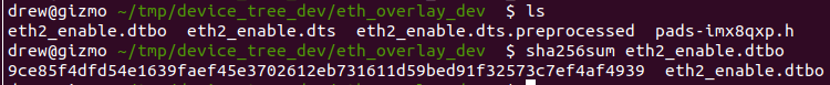
`

How I’m compiling

cpp -nostdinc -I include -I arch -undef -x assembler-with-cpp eth2_enable.dts eth2_enable.dts.preprocess
dtc -o eth2_enable.dtbo eth2_enable.dts.preprocessed

// SPDX-License-Identifier: GPL-2.0-or-later OR MIT
// Enable the ETH2 interface

#include “./pads-imx8qxp.h”

/dts-v1/;
/plugin/;

/ {
compatible = “toradex,colibri-imx8x”;
};

&iomuxc {
pinctrl-names = “default”;
pinctrl-0 = <&pinctrl_hog0>, <&pinctrl_hog1>, <&pinctrl_hog2>,
<&pinctrl_ext_io0>, <&pinctrl_lpspi2_cs2>, <&pinctrl_test>, <&pinctrl_fec2>;

&colibri-imx8qxp {
    /* Ethernet 2 pinctrl group */
    pinctrl_fec2: fec2grp {
        fsl,pins = <
            IMX8QXP_ESAI0_FSR_CONN_ENET1_RCLK50M_OUT    0x06000060
            IMX8QXP_ENET0_MDC_CONN_ENET1_MDC            0x06000060
            IMX8QXP_ENET0_MDIO_CONN_ENET1_MDIO          0x06000060
            IMX8QXP_SPDIF0_RX_CONN_ENET1_RGMII_RXD0     0x00000060
            IMX8QXP_ESAI0_TX3_RX2_CONN_ENET1_RGMII_RXD1 0x00000060
            IMX8QXP_ESAI0_TX2_RX3_CONN_ENET1_RMII_RX_ER 0x00000060
            IMX8QXP_ESAI0_TX4_RX1_CONN_ENET1_RGMII_TXD0 0x00000060
            IMX8QXP_ESAI0_TX5_RX0_CONN_ENET1_RGMII_TXD1 0x00000060
            IMX8QXP_ESAI0_SCKR_CONN_ENET1_RGMII_TX_CTL  0x00000060
        >;
    };
};

};

// Enable FastEthernet 2 interface
&fec2 {
status = “okay”;
pinctrl-names = “default”;
pinctrl-0 = <&pinctrl_fec2>;
phy-mode = “rmii”;
fsl,magic-packet;

mdio {
    #address-cells = <1>;
    #size-cells = <0>;
};

fixed-link {
    speed = <100>;
    full-duplex;
};

};
`

You didn’t copy the answer from the other thread correctly. For the iomuxc node the other thread has:

&iomuxc {
	pinctrl-names = "default";
	pinctrl-0 = <&pinctrl_hog0>, <&pinctrl_hog1>, <&pinctrl_hog2>,
		    <&pinctrl_ext_io0>, <&pinctrl_lpspi2_cs2>, <&pinctrl_test>;

	colibri-imx8qxp {
		pinctrl_test: gpiomuxgrp {
        		fsl,pins = <
            			IMX8QXP_USDHC1_CMD_LSIO_GPIO4_IO24         0x20  /* SODIMM 190 */
        		>;
    		};
	};
};

What you have is:

&iomuxc {
pinctrl-names = “default”;
pinctrl-0 = <&pinctrl_hog0>, <&pinctrl_hog1>, <&pinctrl_hog2>,
<&pinctrl_ext_io0>, <&pinctrl_lpspi2_cs2>, <&pinctrl_test>, <&pinctrl_fec2>;

&colibri-imx8qxp {
    /* Ethernet 2 pinctrl group */
    pinctrl_fec2: fec2grp {
        fsl,pins = <
            IMX8QXP_ESAI0_FSR_CONN_ENET1_RCLK50M_OUT    0x06000060
            IMX8QXP_ENET0_MDC_CONN_ENET1_MDC            0x06000060
            IMX8QXP_ENET0_MDIO_CONN_ENET1_MDIO          0x06000060
            IMX8QXP_SPDIF0_RX_CONN_ENET1_RGMII_RXD0     0x00000060
            IMX8QXP_ESAI0_TX3_RX2_CONN_ENET1_RGMII_RXD1 0x00000060
            IMX8QXP_ESAI0_TX2_RX3_CONN_ENET1_RMII_RX_ER 0x00000060
            IMX8QXP_ESAI0_TX4_RX1_CONN_ENET1_RGMII_TXD0 0x00000060
            IMX8QXP_ESAI0_TX5_RX0_CONN_ENET1_RGMII_TXD1 0x00000060
            IMX8QXP_ESAI0_SCKR_CONN_ENET1_RGMII_TX_CTL  0x00000060
        >;
    };
};

};

Notice the difference in how you organized your colibri-imx8qxp node?

Also why did you assign your pinctrl_fec2 node to the pinctrl-0 of iomuxc? You’re already assigning it to fec2. Plus you copied pinctrl_test to pinctrl-0 of iomuxc, this node doesn’t exist in your setup, this only exists in the context of the other thread.

Best Regards,
Jeremias

// SPDX-License-Identifier: GPL-2.0-or-later OR MIT
// Enable the ETH2 interface

#include "./pads-imx8qxp.h"

/dts-v1/;
/plugin/;

/ {
	compatible = "toradex,colibri-imx8x";
};

&iomuxc {
	pinctrl-names = "default";
	pinctrl-0 = <&pinctrl_hog0>, <&pinctrl_hog1>, <&pinctrl_hog2>,
		    <&pinctrl_ext_io0>, <&pinctrl_lpspi2_cs2>;

    colibri-imx8qxp {
        /* Ethernet 2 pinctrl group */
        pinctrl_fec2: fec2grp {
            fsl,pins = <
                IMX8QXP_ESAI0_FSR_CONN_ENET1_RCLK50M_OUT    0x06000060
                IMX8QXP_ENET0_MDC_CONN_ENET1_MDC            0x06000060
                IMX8QXP_ENET0_MDIO_CONN_ENET1_MDIO          0x06000060
                IMX8QXP_SPDIF0_RX_CONN_ENET1_RGMII_RXD0     0x00000060
                IMX8QXP_ESAI0_TX3_RX2_CONN_ENET1_RGMII_RXD1 0x00000060
                IMX8QXP_ESAI0_TX2_RX3_CONN_ENET1_RMII_RX_ER 0x00000060
                IMX8QXP_ESAI0_TX4_RX1_CONN_ENET1_RGMII_TXD0 0x00000060
                IMX8QXP_ESAI0_TX5_RX0_CONN_ENET1_RGMII_TXD1 0x00000060
                IMX8QXP_ESAI0_SCKR_CONN_ENET1_RGMII_TX_CTL  0x00000060
            >;
        };
    };
};

// Enable FastEthernet 2 interface
&fec2 {
    status = "okay";
    pinctrl-names = "default";
    pinctrl-0 = <&pinctrl_fec2>;
    phy-mode = "rmii";
    fsl,magic-packet;

    mdio {
        #address-cells = <1>;
        #size-cells = <0>;
    };

    fixed-link {
        speed = <100>;
        full-duplex;
    };
};

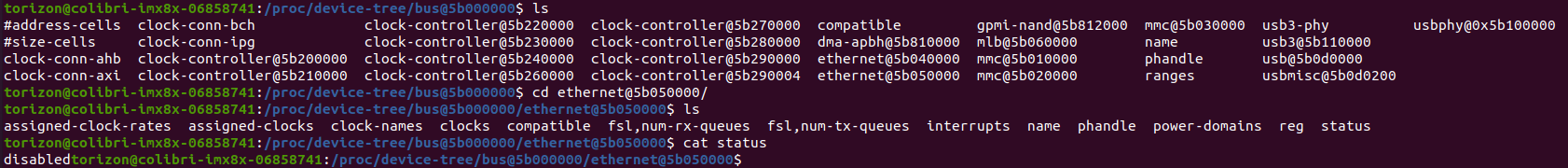
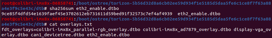
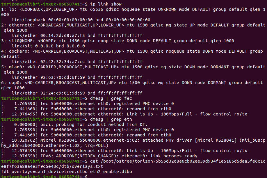
I’ve updated the pin control group with the feedback in the previous post. It compiles now but when I check ethernet@5b050000 in the /proc directory it is still showing the status as disabled. I followed the instructions here Device Tree Overlays on Torizon | Toradex Developer Center.

Is the pin ctrl group correct? Am I checking the status of ethernet2 in the right place?

Do you have any logs from dmesg related to Ethernet that might provide more information?

Also do you actually have anything connected on the other end of this second Ethernet interface?

Is the pin ctrl group correct?

Referencing table 5-7 in the Colibri i.MX8X datasheet, your pins in your pinctrl group don’t perfectly match. Could you comment on this difference.

Best Regards,
Jeremias

There is no mention of eth2 in dmesg.


This is the directory where I compiled the overlay.

This is what is currently in the overlay directory on the board.

I used the pins listed by the Toradex pinout designer. I have tried both RCLK50M_IN (pinout designer tool) and RCLK50M_OUT (iMX8X datasheet).

I am not sure about the hex values listed after the pins in the pin ctrl group. I used an example from another forum post to set those. Are those the correct values?

I see you have other overlays applied related to parallel RGB and such. I’m fairly sure some of the pins used in the parallel RGB interface are being used in your 2nd Ethernet interface. You might be experiencing a pin conflict in that case since 2 interfaces are requesting the same pin(s). This can cause the affected systems to behave unpredictably or just not work at all.

You need to either resolve the conflict by not using conflicting pins or disable one of the interfaces so there is no conflict over pins.

Best Regards,
Jeremias


I removed all of the other overlays except for one we are using to activate CAN1. The pinout designer says there are no conflicts with the can overlay. If there are pin conflicts shouldn’t the status still be changed?

Just to clarify is there anything actually on the other end of this Ethernet interface? Looking at your overlay it seems like you defined and configured the interface but didn’t specify any devices on that interface.

I don’t know if the interface will just show up as enabled or do anything if there’s nothing on it.

Best Regards,
Jeremias

I had an ethernet cable pulled into the interface if that is what you are asking.

I found this in the repo below.

image
Even if nothing is plugged in the status should still be set to okay for ethernet@5b050000 shouldn’t it?

I had an ethernet cable pulled into the interface if that is what you are asking.

Could you clarify what you mean by this? Do you have a custom carrier board that has a Ethernet PHY or something similar hooked up to the pins of this second interface? The interface on it’s own doesn’t do much unless it’s hooked up to something.

Even if nothing is plugged in the status should still be set to okay for ethernet@5b050000 shouldn’t it?

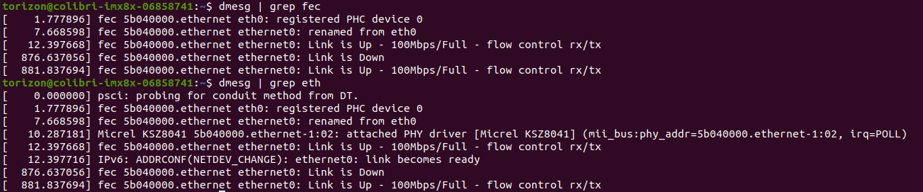
This largely depends on the behavior of the software driver and what it considers “okay” for status. Since you’re not seeing any logs in dmesg related to fec2 this leads me to believe nothing is happening on this interface which is why I’m asking about your hardware configuration.

Best Regards,
Jeremias

We are using a custom carrier board with a LAN8719A RMII PHY configured for address 01 attached to eth2.

Ok so this sounds like you have an RMII type PHY connected to the 2nd Ethernet interface via MDIO I assume correct?

In that case you need to modify your overlay a bit more. In your current overlay I don’t see any description for this PHY. As a reference see how we define the RMII PHY built into our module in the fec1 node here: imx8x-colibri.dtsi « freescale « dts « boot « arm64 « arch - linux-toradex.git - Linux kernel for Apalis, Colibri and Verdin modules

&fec1 {
	pinctrl-names = "default", "sleep";
	pinctrl-0 = <&pinctrl_fec1>;
	pinctrl-1 = <&pinctrl_fec1_sleep>;
	phy-mode = "rmii";
	phy-handle = <&ethphy0>;
	fsl,magic-packet;
	fsl,wakeup_irq = <0>;

	mdio {
		#address-cells = <1>;
		#size-cells = <0>;

		ethphy0: ethernet-phy@2 {
			compatible = "ethernet-phy-ieee802.3-c22";
			max-speed = <100>;
			reg = <2>;
		};
	};
};

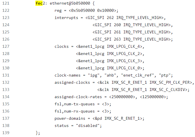
I imagine your desired use-case is similar to what we have on the fec1 node by default. Of course you’ll need to adjust this based on the actual parameters of your specific PHY.

Finally I was comparing your pinctrl group to the one used for fec1:

pinctrl_fec1: fec1grp {
			fsl,pins = <
				IMX8QXP_COMP_CTL_GPIO_1V8_3V3_ENET_ENETB0_PAD	0x000014a0 /* Use pads in 3.3V mode */
				IMX8QXP_COMP_CTL_GPIO_1V8_3V3_ENET_ENETB1_PAD	0x000014a0 /* Use pads in 3.3V mode */
				IMX8QXP_ENET0_MDC_CONN_ENET0_MDC		0x06000020
				IMX8QXP_ENET0_MDIO_CONN_ENET0_MDIO		0x06000020
				IMX8QXP_ENET0_RGMII_TX_CTL_CONN_ENET0_RGMII_TX_CTL	0x61
				IMX8QXP_ENET0_RGMII_TXC_CONN_ENET0_RCLK50M_OUT	0x06000061
				IMX8QXP_ENET0_RGMII_TXD0_CONN_ENET0_RGMII_TXD0	0x61
				IMX8QXP_ENET0_RGMII_TXD1_CONN_ENET0_RGMII_TXD1	0x61
				IMX8QXP_ENET0_RGMII_RX_CTL_CONN_ENET0_RGMII_RX_CTL	0x61
				IMX8QXP_ENET0_RGMII_RXD0_CONN_ENET0_RGMII_RXD0	0x61
				IMX8QXP_ENET0_RGMII_RXD1_CONN_ENET0_RGMII_RXD1	0x61
				IMX8QXP_ENET0_RGMII_RXD2_CONN_ENET0_RMII_RX_ER	0x61
			>;
		};

The pinmuxing values after each pin are a bit different than what you have for your pinctrl group.

In summary I would suggest to try and model your fec2 node and pinctrl group to closer resemble the pre-existing fec1 node since it seems your hardware use-case is similar enough. That and we know fec1 works properly as is.

Best Regards,
Jeremias

I am not sure how to handle the naming in the mdio section. Would I increment the values from the mdio section of fec1 like ethphy1: ethernet-phy@3 or are those values set somewhere else? Will the reg value be incremented so it would be reg = <3>?

I have undated the pinmuxing values in the pinctrl group to match whats in pinctrl_fec1.

colibri-imx8qxp {
pinctrl_fec2: fec2grp {
fsl,pins = <
IMX8QXP_ESAI0_FSR_CONN_ENET1_RCLK50M_IN 0x06000061
IMX8QXP_ENET0_MDC_CONN_ENET1_MDC 0x06000020
IMX8QXP_ENET0_MDIO_CONN_ENET1_MDIO 0x06000020
IMX8QXP_SPDIF0_RX_CONN_ENET1_RGMII_RXD0 0x61
IMX8QXP_ESAI0_TX3_RX2_CONN_ENET1_RGMII_RXD1 0x61
IMX8QXP_ESAI0_TX2_RX3_CONN_ENET1_RMII_RX_ER 0x61
IMX8QXP_ESAI0_TX4_RX1_CONN_ENET1_RGMII_TXD0 0x61
IMX8QXP_ESAI0_TX5_RX0_CONN_ENET1_RGMII_TXD1 0x61
IMX8QXP_ESAI0_SCKR_CONN_ENET1_RGMII_TX_CTL 0x61
>;
};
};

I found this post. Is it close to what needs to be added?

I

Would I increment the values from the mdio section of fec1 like ethphy1: ethernet-phy@3 or are those values set somewhere else? Will the reg value be incremented so it would be reg = <3>?

The numbers pertain to the PHY’s address on the MDIO interface. For example our PHY on fec1 has an address of “00010” (in binary) which is translates to “2” (in decimal) that you see in the device tree. Earlier you mentioned your PHY has an address of 00001 which is just 1.

Best Regards,
Jeremias

You must have and mdio section
with reg = <1>; //according to your PHY strapping

Please also check next threads:

I have updated the overlay with some of the suggestions from previous posts and the ones referenced. I have attached if to review. The pinmux values match fec1 now. I am still not seeing anything when I run dmesg | grep eth for a second ethernet interface.

Do I need to do anything for the power pin? I noticed them referenced in fec1 and in one of the other posts and added them but I’m not sure what else needs to be done.
eth2_enable.dts (1.7 KB)

Unfortunately I can’t debug your issue without a hardware with second Phy. Could you please try to post your question on NXP community?