hi @MariusM ,
which display will you use?
As I mentioned before, it is important to understand the underlying hardware connection since device tree is a way to describe/“introduce” your hardware to the kernel so that it can get the correct driver and use the hardware correctly.
I don’t have experience with eDP display yet, but we can take the example from MNT Reform 2 given by @hfranco.tx as it is a grea example of open source hardware with good documentation: MNT Reform Operator Handbook — MNT Reform Operator Handbook documentation. They successfully tested some eDP displays too: Parts — MNT Reform Operator Handbook documentation.
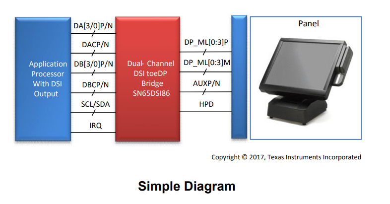
Now we take a step back and look at the block diagram of the hardware. This is taken from TI SN65DSI86 datasheet:
Now, comparing this with your board then we identify:
- Application Processor: we target Colibri iMX8X + Iris
- The bridge itself
- Panel: your intended display
Each of the hardware components should be described in the device tree according to the “binding” documentation (the link points to toradex_5.15-2.2.x-imx branch for our BSP 6). Some useful bindings to understand how to write the device tree:
- ti,sn65dsi86.yaml « bridge « display « bindings « devicetree « Documentation mentioned by @hfranco.tx previously
- Generic binding for display panel: panel-common.yaml « panel « display « bindings « devicetree « Documentation
- Example of an eDP display: innolux,p120zdg-bf1.yaml « panel « display « bindings « devicetree « Documentation
Take your time to read and understand them. The bindings usually give example and minimum required properties to be described in the device tree. This is in general important to work with device tree.
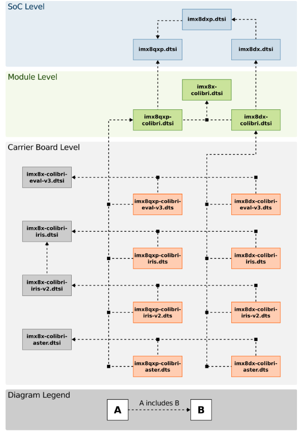
For the component 1 above (Colibri iMX8X + Iris), there is no binding, but obviously you can use the.dts directly. And refer to the diagram given here. It is very useful to understand our board definition and the blocks are clickable directly to the source code.
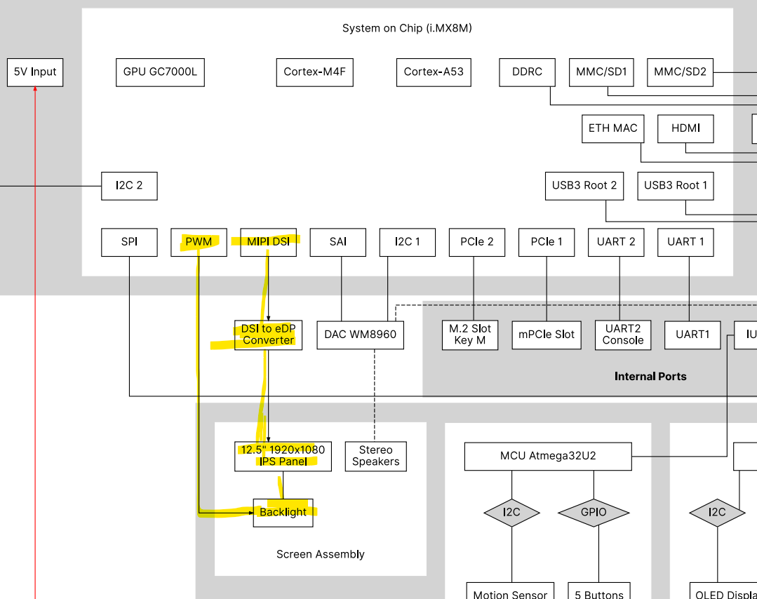
Now we try to compare this with the system diagram from MNT Reform 2 and we focus on the display part:
.
We see in this example that the display is connected to the bridge and also PWM for the backlight from the SoC and when we study the device tree of the MNT Reform 2 (and the bindings before), we see some important nodes accordingly:
/ {
...
/* you also find this node in https://git.toradex.com/cgit/linux-toradex.git/tree/arch/arm64/boot/dts/freescale/imx8x-colibri.dtsi?h=toradex_5.15-2.2.x-imx */
backlight: backlight {
compatible = "pwm-backlight";
pinctrl-names = "default";
pinctrl-0 = <&pinctrl_backlight>;
pwms = <&pwm2 0 10000 0>;
power-supply = <®_main_usb>;
enable-gpios = <&gpio1 10 GPIO_ACTIVE_HIGH>;
brightness-levels = <0 32 64 128 160 200 255>;
default-brightness-level = <6>;
};
/* compare the following with example from https://git.toradex.com/cgit/linux-toradex.git/tree/Documentation/devicetree/bindings/display/panel/innolux,p120zdg-bf1.yaml?h=toradex_5.15-2.2.x-imx)*/
panel {
compatible = "innolux,n125hce-gn1";
power-supply = <®_main_3v3>;
backlight = <&backlight>;
no-hpd;
port {
panel_in: endpoint {
remote-endpoint = <&edp_bridge_out>;
};
};
};
reg_main_3v3: regulator-main-3v3 {
compatible = "regulator-fixed";
regulator-name = "3V3";
regulator-min-microvolt = <3300000>;
regulator-max-microvolt = <3300000>;
};
reg_main_usb: regulator-main-usb {
compatible = "regulator-fixed";
regulator-name = "USB_PWR";
regulator-min-microvolt = <5000000>;
regulator-max-microvolt = <5000000>;
vin-supply = <®_main_5v>;
};
reg_main_1v8: regulator-main-1v8 {
compatible = "regulator-fixed";
regulator-name = "1V8";
regulator-min-microvolt = <1800000>;
regulator-max-microvolt = <1800000>;
vin-supply = <®_main_3v3>;
};
reg_main_1v2: regulator-main-1v2 {
compatible = "regulator-fixed";
regulator-name = "1V2";
regulator-min-microvolt = <1200000>;
regulator-max-microvolt = <1200000>;
vin-supply = <®_main_5v>;
};
sound {
compatible = "fsl,imx-audio-wm8960";
audio-cpu = <&sai2>;
audio-codec = <&wm8960>;
audio-routing =
"Headphone Jack", "HP_L",
"Headphone Jack", "HP_R",
"Ext Spk", "SPK_LP",
"Ext Spk", "SPK_LN",
"Ext Spk", "SPK_RP",
"Ext Spk", "SPK_RN",
"LINPUT1", "Mic Jack",
"Mic Jack", "MICB",
"LINPUT2", "Line In Jack",
"RINPUT2", "Line In Jack";
model = "wm8960-audio";
};
};
/* this seems also to be important if your display has speaker and you want to enable it */
&i2c3 {
pinctrl-names = "default";
pinctrl-0 = <&pinctrl_i2c3>;
status = "okay";
wm8960: codec@1a {
compatible = "wlf,wm8960";
reg = <0x1a>;
clocks = <&clk IMX8MQ_CLK_SAI2_ROOT>;
clock-names = "mclk";
#sound-dai-cells = <0>;
};
rtc@68 {
compatible = "nxp,pcf8523";
reg = <0x68>;
};
};
/* I would say this is the most important node between the SoC and the bridge. Pay close attention to all labels in the phandle too (everything that starts with &) */
&i2c4 {
pinctrl-names = "default";
pinctrl-0 = <&pinctrl_i2c4>;
clock-frequency = <400000>;
status = "okay";
edp_bridge: bridge@2c {
compatible = "ti,sn65dsi86";
pinctrl-names = "default";
pinctrl-0 = <&pinctrl_edp_bridge>;
reg = <0x2c>;
enable-gpios = <&gpio3 20 GPIO_ACTIVE_HIGH>;
vccio-supply = <®_main_1v8>;
vpll-supply = <®_main_1v8>;
vcca-supply = <®_main_1v2>;
vcc-supply = <®_main_1v2>;
ports {
#address-cells = <1>;
#size-cells = <0>;
port@0 {
reg = <0>;
edp_bridge_in: endpoint {
remote-endpoint = <&mipi_dsi_out>;
};
};
port@1 {
reg = <1>;
edp_bridge_out: endpoint {
remote-endpoint = <&panel_in>;
};
};
};
};
};
&mipi_dsi {
status = "okay";
ports {
port@1 {
reg = <1>;
mipi_dsi_out: endpoint {
remote-endpoint = <&edp_bridge_in>;
};
};
};
};
&pwm2 {
pinctrl-names = "default";
pinctrl-0 = <&pinctrl_pwm2>;
status = "okay";
};
&sai2 {
pinctrl-names = "default";
pinctrl-0 = <&pinctrl_sai2>;
assigned-clocks = <&clk IMX8MQ_CLK_SAI2>;
assigned-clock-parents = <&clk IMX8MQ_CLK_25M>;
assigned-clock-rates = <25000000>;
fsl,sai-mclk-direction-output;
fsl,sai-asynchronous;
status = "okay";
};
&iomuxc {
pinctrl_backlight: backlightgrp {
fsl,pins = <
MX8MQ_IOMUXC_GPIO1_IO10_GPIO1_IO10 0x3
>;
};
pinctrl_edp_bridge: edpbridgegrp {
fsl,pins = <
MX8MQ_IOMUXC_SAI5_RXC_GPIO3_IO20 0x1
>;
};
pinctrl_i2c4: i2c4grp {
fsl,pins = <
MX8MQ_IOMUXC_I2C4_SCL_I2C4_SCL 0x40000022
MX8MQ_IOMUXC_I2C4_SDA_I2C4_SDA 0x40000022
>;
};
pinctrl_pwm2: pwm2grp {
fsl,pins = <
MX8MQ_IOMUXC_SPDIF_RX_PWM2_OUT 0x3
>;
};
pinctrl_sai2: sai2grp {
fsl,pins = <
MX8MQ_IOMUXC_SAI2_RXD0_SAI2_RX_DATA0 0xd6
MX8MQ_IOMUXC_SAI2_RXFS_SAI2_RX_SYNC 0xd6
MX8MQ_IOMUXC_SAI2_TXC_SAI2_TX_BCLK 0xd6
MX8MQ_IOMUXC_SAI2_TXFS_SAI2_TX_SYNC 0xd6
MX8MQ_IOMUXC_SAI2_RXC_SAI2_RX_BCLK 0xd6
MX8MQ_IOMUXC_SAI2_MCLK_SAI2_MCLK 0xd6
MX8MQ_IOMUXC_SAI2_TXD0_SAI2_TX_DATA0 0xd6
>;
};
};
After studying, now it’s time for work. So, as an overview to get started:
- Use the example above as templates - keep those nodes and labels in mind because we want to implement them
- Write your own .dts (e.g.
my-colibri-imx8x-iris-edp.dts based on imx8qxp-colibri-iris-v2.dts or imx8dx-colibri-iris-v2.dts) for your carrier board and create such nodes if it is not available
- Adapt the labels and property values according to your specification/our module specification (our device tree)
Don’t change any of our .dtsi as this can change when we update our board in the future. Keep all changes in your own .dts.
I don’t have eDP display with the bridge to test but I think that’s all about what I learned through that MNT Reform 2 example.
Of course, this is not meant to be a comprehensive step-by-step how-to, but I hope this gives a better idea for you. You will still need to invest some time and do many trial-and-errors (grab coffee or take a walk as always if you are frustrated  ).
).
It’s your turn now to let us know how it works and share your findings. Let us know if you have issues.