Currently we are using verdin imx8 plus development board for our application
We are making our own custom carrier board in which we planning to use mipi dsi to RGB parallel interface. As per Verdin Carrier Board Design Guide the DSI to parallel RGB bridge TC358867XBG from Toshiba is recomended by toradex. I didn’t see any .dtbo file in my overlay directory to enable it and also the driver for this IC.
Please suggest necessary modifications in the kernal build and device tree
I am using yocto based linux bulid
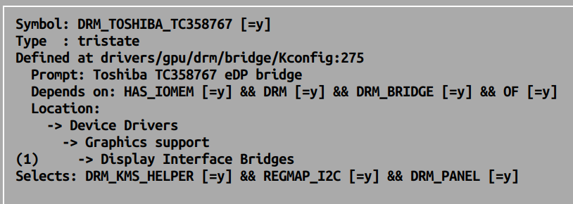
You need to include corresponding driver into the kernel by configuring CONFIG_DRM_TOSHIBA_TC358767 = y.
And also modify a Device tree. Please check this article for some details.
Thank you for your quick reply
I didn’t find CONFIG_DRM_TOSHIBA_TC358767 this option in my config file (i.e.,
$HOME/yocto-build/bsp-toradex/build/tmp/work-shared/verdin-imx8mp/kernel-source/arch/arm64/configs/toradex_defconfig)
Please sugesst…
DSI to RGB adapter is work in progress, that is the reason BSP do not have any support for same and we do not have exact device tree configuration for same.
I will suggest, to build kernel and dtb outside yocto development, this give you more control and is simpler for testing device tree and kernel.
Once driver and device tree modification freeze, then include those changes with yocto to generate final image.
Detail on how to compile kernel and device tree is explained here.
After configuring terminal for cross compiling and cloning kernel source, issue below command and select Toshiba chip driver
~linux-toradex$ make toradex_defconfig
~linux-toradex$ make menuconfig
~linux-toradex$ make -j$(nproc) Image.gz 2>&1 | tee build.log
~linux-toradex$ make DTC_FLAGS="-@" freescale/imx8mp-verdin-nonwifi-dev.dtb
After above, you will need to add respective device tree for TC358767. Refer this article for details on device tree overlay and this article for how to write device tree overlay. Make one dtbo for your bridge take reference from link shared in first reply.
Let me know if you have have any query.
Best Regards
Ritesh Kumar
As @ritesh.tx motioned we do not have such device tree and therefore no file path for yocto built. But you can create your own one based on this article .
We designed our custom board using Toshiba IC (i.e., TC358867XBG ) for DSI to parallel RGB bridge by taking reference of verdin design document
But I didn’t find any driver files related to this IC (i.e., TC358867XBG ) neither in the kernel source code nor in the config file
In the above post you suggested to configure CONFIG_DRM_TOSHIBA_TC358767 IC , will it compatible with TC358867XBG IC ?
As I can check comparing both datasheets and found no pin compatibility.
Can you please confirm if you are refering to downstream or upstream kernel?
Quickly checking driver code at drivers/gpu/drm/bridge/tc358767.c, there is mention of specified partnumber. So I assume that this chip will be supported, but since we never tested we are not sure about efforts required to get same running.
* TC358767/TC358867/TC9595 DSI/DPI-to-DPI/(e)DP bridge driver
 *
 * The TC358767/TC358867/TC9595 can operate in multiple modes.
 * All modes are supported -- DPI->(e)DP / DSI->DPI / DSI->(e)DP .
Let me know if you have further query.
Best Regards
Ritesh Kumar
Thanks for conformation
I am referring to downstream kernal
I have done following modifications in imx8mp-verdin.dtsi file for mipi dsi to Rgb parallel data interface
Please cross check and let me know if any modifications needed
/* Verdin I2C_2_DSI /
&i2c2 {
/ Lower frequency to avoid DDC/EDID issues with certain displays/screens. */
clock-frequency = <10000>;
pinctrl-names = “default”, “gpio”;
pinctrl-0 = <&pinctrl_i2c2>;
pinctrl-1 = <&pinctrl_i2c2_gpio>;
scl-gpios = <&gpio5 16 (GPIO_ACTIVE_HIGH | GPIO_OPEN_DRAIN)>;
sda-gpios = <&gpio5 17 (GPIO_ACTIVE_HIGH | GPIO_OPEN_DRAIN)>;
This looks okay but without knowing what all pins you are using and how are you connecting it is bit difficult to comment further.
Also please share git diff output so that we can see complete changes.
With above modification (i.e.,imx8mp-verdin.dtsi file ) toshiba tc358767 driver file is loaded and I have verified I2C transaction
But the clock and data from processor (i.e., mipi_dsi interface) is not coming
Could you please suggest how to link mipi_dsi out from processor to toshiba IC input
I will share the schematic through email for your reference