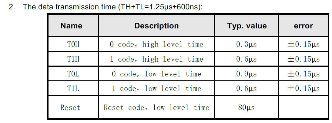
Hello. I am trying to interface a IN-PI554FCH LED with a colibri-imx8x. In order to set the appropriate color on the LED I need to send it pulses as mentioned in the table below:
To achieve the required timings I am hoping to use either PWM or the SPI Bus. If I were to use the SPI bus; is the a library exposed to the user space which I can use to write the values I need on the bus or do I need to write my own custom driver in the kernel space?
On raspberry Pi there is a pigpio library which can be used to control SPI/I2C/PWM is there something like that available for the Toradex NXP modules ?
The described protocol is highly similar (and likely compatible) with the protocol used by the ws2812b LED. You definitely cannot drive this LED via SPI/I2C/PWM or user space GPIO manipulation. However, you could attempt to use one of the available drivers for the ws2812b LED, like this one or something similar. Another approach is to incorporate a microcontroller into your carrier board that will control your LED strip and communicate with Colibri via UART/SPI/I2C. A third option is to use the iMX8x dedicated M core.
It seems from the source code the ws2812b driver is using the spi bus to create the wave from needed. Its expecting the user to define a spi_init_10Mhz function.
How would I go about setting this up? MX8x dedicated M core. Do you have any documentation you can point me to ?
How many such LEDs in a row are you going to use? Just a single one? Using right SPI, you would need 4 SPI clock pulses for one TH+TL bit, b1000 for “0” and b1100 for “1”. Required SPI clock is 4/1.2us = 3.3MHz. Driving one such LED, SPI has to be able to shift out 24*4=96 bits at uniform SPI clock, without unexpected pauses between adjacent bytes. Should be easy with any FIFO equipped SPI controller.
Driving a row of such LEDs may be more complicated due to possible single transfer limit. eCSPI (not sure, perhaps not applicable to your imx8x) is limited at 2048 bits without DMA, or 2048/4/24 ~ about 20 LEDs in a row.
I am going down the route of using the M Core. I was able to download and compile the freertos_hello example from NXP. I copied the compiled freertos_hello.bin file into the /boot directory. I am having trouble running the binary from uboot. I don’t see any documentation regarding running the binary from uboot.
Can you please provide the commands I need to run ?
Got it. I am able to run a led_output program in the microcontroller. The program is using GPIO_PinWrite(EXAMPLE_LED_GPIO, EXAMPLE_LED_GPIO_PIN, 0U) to set/reset the gpio pin which is taking about 500ns. To drive the LED the I need to be able to go high for 300ns. Is there a way for me to directly access the gpio registers to set the pin high/low ?
Yes, generally, you can write to GPIO registers directly to speed up the process . However, please remember that direct register access is usually not recommended due to the potential for bugs and system instability. For details about GPIO registers, please refer to Chapter 12.6, Rapid General-Purpose Input and Output (RGPIO), in the i.MX 8DualX/8DualXPlus/8QuadXPlus Applications Processor Reference Manual.
With big row of LEDs Cortex-M still may be required even with SPI. It is about real time. If you need few SPI transfers without unpredictable gaps of up to many milliseconds (on Linux), then you still need real time helper like external MCU or secondary Cortex-M. Speaking about eCSPI Linux driver, you may experience another problem of about ~1us gap between adjacent SPI bytes/words.
3 LEDs are fine with eCSPI and Linux. Ehh, was fine with older eCSPI driver, which allowed to send up to 64 bytes without any SCK glitches (~1us gaps). Latest NXP driver in their donwstream 6.1 seems reducing that limit … to just one byte… I’m not sure which eCSPI driver version do you have. Just try it with spidev driver and user space spidev-test utility, which you could use to control your LEDs from user space, like some bash script to prepare SPI data and a spidev-test call to send SPI data. You need nice, no gaps SPI SCK for 2434 bits = 36 byte long transfer. (3 leds, 24 TH+TL bits each, 4 SPI bits for one TH-TL pulse). Required for your LED 4/1.2us = 3.3MHz SPI clock shouldn’t be a problem.
I was able to get the GPIO pin to toggle by accessing the register directly. I am seeing something strange though:
Given the code below I am seeing on the scope that the GPIO is staying high for about 500ns and then low for about 500ns. As per the led spec I need to stay high for 300ns before going low. Is there a clock setting some where that needs to be configured to achieve better timing ?
What is the purpose of using addressable LEDs? If you only require three such LEDs, it might be simpler to utilize three standard RGB LEDs and operate them using nine GPIO lines, or alternatively, trough I2C/SPI GPIO extender.
I was able to get the LEDs to work using the RGPIO pin . I am able to toggle at 50ns which meets the specs I need. I am having a strange issue though, I have a custom image based off the Kirkstone branch for colibri imx8x in Uboot I am missing the bootaux command. How do I go about enabling bootaux in uboot ?