While building up a custom carrier board, we have been prototyping with a TPM breakout board (STPM4RasPi) connected to a Colibri iMX8x on Iris V2. We had initially been using the breakout with a Raspberry Pi prior to ordering our supplies from Toradex, which proved our use of the TPM for our application and provides a point of comparison for driving the breakout board.
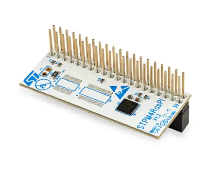
As indicated in the photo of the breakout, the header matches the Raspberry Pi. This requires us to use jumper wires to connect to the Iris V2 carrier. The variant of the TPM chip is SPI, which is exposed on X16 of the Iris V2 board. There are other signals that need to be managed in addition to the SPI bus:
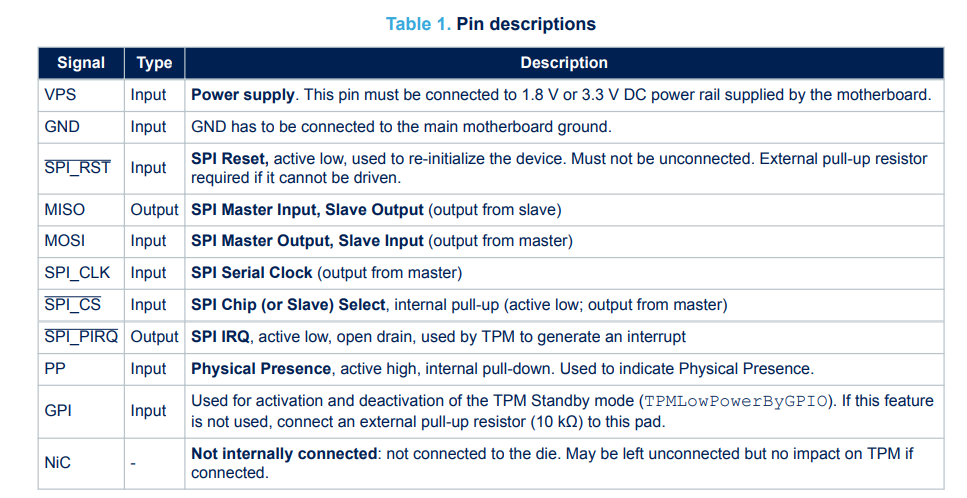
We opted to pull up /SPI_RST and PP with a 10k resister instead of driving these from other GPIO pins. This configuration was validated with the same Raspberry Pi by connecting only the SPI bus with jumper wires.
On the software side, we have configured the base OS to use the Iris V2 device tree:
greg@KLARIAN-0010:~/Torizon/tcbworkdir$ torizoncore-builder dt status
Current device tree is: imx8qxp-colibri-iris-v2.dtb
We have an additional overlay applied that disables spidev0 and enables st33htpm0:
greg@KLARIAN-0010:~/Torizon/tcbworkdir$ torizoncore-builder dto status
Enabled overlays over device tree imx8qxp-colibri-iris-v2.dtb:
- colibri-imx8x_st33htpm_overlay.dtbo
// STMicro ST33TPH TPM device on SPI bus.

/dts-v1/;
/plugin/;

/ {
        compatible = "toradex,colibri-imx8x";
};

&spidev0 {
        status = "disabled";
};

&lpspi2 {
        status = "okay";

        tpm0: st33htpm@0 {
                compatible = "st,st33htpm-spi", "tcg,tpm_tis-spi";
                reg = <0>;
                #address-cells = <1>;
                #size-cells = <0>;
                spi-max-frequency = <10000000>;
                status = "okay";
        };
};
This results in two SPI nodes being created on the lpspi2 device:
torizon@colibri-imx8x-07268698:/proc/device-tree/bus@5a000000/spi@5a020000$ ls
#address-cells  assigned-clock-rates  clock-names  compatible  dma-names  interrupt-parent  name     pinctrl-0      power-domains  spidev@0    status
#size-cells     assigned-clocks       clocks       cs-gpios    dmas       interrupts        phandle  pinctrl-names  reg            st33htpm@0
torizon@colibri-imx8x-07268698:/proc/device-tree/bus@5a000000/spi@5a020000$ cat spidev@0/status ; echo
disabled
torizon@colibri-imx8x-07268698:/proc/device-tree/bus@5a000000/spi@5a020000$ cat st33htpm@0/status ; echo
okay

torizon@colibri-imx8x-07268698:/sys/bus/spi/devices/spi0.0$ cat uevent
OF_NAME=st33htpm
OF_FULLNAME=/bus@5a000000/spi@5a020000/st33htpm@0
OF_COMPATIBLE_0=st,st33htpm-spi
OF_COMPATIBLE_1=tcg,tpm_tis-spi
OF_COMPATIBLE_N=2
MODALIAS=spi:st33htpm-spi
From here, we install the kernel module to initiate SPI communication with the TPM:
torizon@colibri-imx8x-07268698:~$ sudo modprobe tpm_tis_spi
Password:
torizon@colibri-imx8x-07268698:~$ lsmod
Module                  Size  Used by
tpm_tis_spi            16384  0
tpm_tis_core           28672  1 tpm_tis_spi
tpm                    77824  2 tpm_tis_core,tpm_tis_spi
However, the kernel is unable to bring up /dev/tpm0 because of a failure to communicate with the TPM device. Using an oscilloscope, we see that the SPI transactions are one-sided. The TPM never drives the MISO line.


For comparison, this is a capture of the same configuration but connected to the Raspberry Pi SPI bus.

While researching the issue, we found a post in the forum that indicated some changes to the kernel module being required to make an Infineon TPM complete the initialisation. However, the description of the fix lacked detail.
Is there a configuration element that was missed when moving from the Raspberry Pi to the Colibri? Or do we need to look at modifying the kernel module as described for the Infineon TPM?