Hi @steve274,
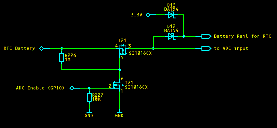
I would like to add my two cents to this discussion. Connecting the RTC battery over an 1M resistor to the ADC could cause two issues: If you use the AD1 input of the module (pin 6), the STMPE811 could get strapped to SPI instead of I2C which means it is not possible to communicate with the device anymore. Therefore, I highly recommend to use any of the other 3 ADC inputs of the module (AD0, AD2, or AD3 on pin 8, 4, or 2). The second one is that there will be a back feeding to the module while the module is shut down. In worst case, there will be around an extra 3uA current consumption in the battery. This is definitely not helping to keep the battery alive for a longer time. Therefore, I would recommend to add a circuit which allows to disconnect the battery from the ADC. Only connect it when you want to measure the voltage (which probably happens only once in a wile anyway). Maybe this little circuit could help. I have just drawn it, it is not validated:
The typical IDD_BATT current consumption of the Colibri iMX6 is around 45uA to 50uA. This is indeed not really great. A CR1220 battery will not last very long with the on-module RTC. Therefore, we highly recommend an external RTC IC on the carrier board instead. Such external devices will consume dramatically less current (e.g. 0.9uA) which will increase the battery life span. Under ideal conditions, you should be able to reach even years of battery life. If you use such an external RTC device, the VCC_BATT of the module can be connected directly to the regular 3.3V rail. Do not connect the VCC_BATT pin to the RTC battery in this case. Please see also figure 26 in section 3.2 of the Colibri Carrier Board Design Guide.