Is there any way to determine if the RTC backup battery is flat, either directly or by attaching the battery +ve voltage to an ADC? Accurate timestamps are essential to the correct running of our application.
Sure, you can connect ADC pin to backup battery through 1M resistor and use an embedded ADC to measure RTC battery voltage.
The RTC on the module is not designed for ultra-low power consumption. Typical V_Batt consumption is around 45 µA. Thus CR2032 battery will last only around 20 days if board is not powered.
If a rechargeable RTC battery is not a solution, it is recommended to use an external ultra-low power RTC IC on the carrier board instead.
Hi @alex.tx,
Thanks for the reply.
The Iris takes a CR1220 with around 1/6 the capacity of a CR2032 at ~37mAh. The datasheet for the RTC gives a standby current of 0.9uA which would give a battery life of over 100 days (I appreciate that is under ideal conditions!). In our experience the RTC batteries usually have a much better lifespan than 20 days.
What rechargeable batteries do you recommend for the Iris board?
Hi @steve274,
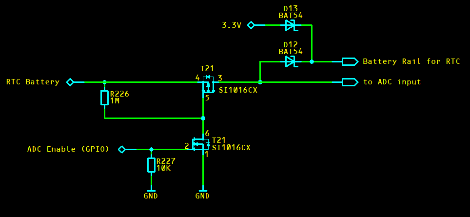
I would like to add my two cents to this discussion. Connecting the RTC battery over an 1M resistor to the ADC could cause two issues: If you use the AD1 input of the module (pin 6), the STMPE811 could get strapped to SPI instead of I2C which means it is not possible to communicate with the device anymore. Therefore, I highly recommend to use any of the other 3 ADC inputs of the module (AD0, AD2, or AD3 on pin 8, 4, or 2). The second one is that there will be a back feeding to the module while the module is shut down. In worst case, there will be around an extra 3uA current consumption in the battery. This is definitely not helping to keep the battery alive for a longer time. Therefore, I would recommend to add a circuit which allows to disconnect the battery from the ADC. Only connect it when you want to measure the voltage (which probably happens only once in a wile anyway). Maybe this little circuit could help. I have just drawn it, it is not validated:
The typical IDD_BATT current consumption of the Colibri iMX6 is around 45uA to 50uA. This is indeed not really great. A CR1220 battery will not last very long with the on-module RTC. Therefore, we highly recommend an external RTC IC on the carrier board instead. Such external devices will consume dramatically less current (e.g. 0.9uA) which will increase the battery life span. Under ideal conditions, you should be able to reach even years of battery life. If you use such an external RTC device, the VCC_BATT of the module can be connected directly to the regular 3.3V rail. Do not connect the VCC_BATT pin to the RTC battery in this case. Please see also figure 26 in section 3.2 of the Colibri Carrier Board Design Guide.
Thanks for the detailed reply @peter.tx, that’s really helped us decide which way to go with this. I have two further queries:
Please could you confirm that no current is drawn from the battery while the Colibri is powered on?
And would it be possible to replace the CR1220 with a large capacity (~1500mAh) external Lithium Manganese Dioxide 3V battery such as a CR123 (with suitable wiring)?
Hi @steve274 ,
There is no current drawn from the battery if the circuit on the carrier board is correctly done. The module itself requires the VCC_BATT also while the module is running. The consumption is even slightly higher than in the off state. Beside the on-module RTC, the VCC_BATT is also used for the SoC power management state machine. This state machine for example has an output signal to the PMIC for starting the power up sequence. This is the reason why the module also requires the VCC_BATT rail, even if the on-module RTC is not in use.
In order to make sure there is no current draw from the battery while the module is running, we recommend adding two diodes. You see these diodes in my drawing or in the schematics of the evaluation board. Since the battery voltage is normally lower than 3.3V, the VCC_BATT will be sourced from the 3.3V rail as soon as this rail is available.
Theoretically, it would be possible to use one of these CR123 batteries. The maximum input voltage rating for the VCC_BATT is 3.6V. The drawback with this battery could be that a fresh battery can have up to 3.25V. This means if the 3.3V rail is slightly lower (3.135V is still in the tolerance), the two diode circuit is not working fine anymore. The current for the VCC_BATT will be drawn from the CR123 battery instead of the 3.3V rail. However, this should not be a big issue since it anyway only happens when the CR123 is very fresh.
You maybe also need to consider self discharging of the CR123. I do not know how much that is, but when we assume you have only the external RTC with a consumption of 0.9uA, this would give a theoretical battery lifespan of 190 years. I doubt that CR123 will be able to do that. It would be interesting to know what the self discharge of such a battery is. Maybe you do not get a much longer battery lifespan than with a regular CR2032. But of curse, if the consumption is higher than 0.9uA, the CR123 would be beneficial whit its seven times higher capacity.
Thanks for the reply again @peter.tx . After a lot of discussion we have decided to handle low battery conditions in software by examining the system time at startup rather than measuring the battery voltage while running, to avoid having to make major changes to our hardware at this time.
Thank you for an update. Do you mind to discuss your software solution here?
We have an AutoRun program which runs before the main programs, which looks at the system time at startup. If the year is before 2018 we assume a flat battery and create a file called LowBattery. If the year is 2018 or later, we delete the file. When other programs are run later, they can check to see if the file exists, and if so, refuse to accept commands and warn the user. If the time is reset correctly by a later process, the file is deleted so that normal operations can resume.