Hi,
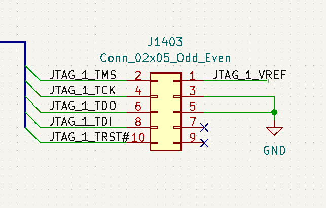
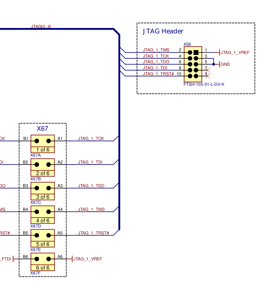
I am trying to use a Segger J-Link to debug my Verdin-Mini on the Dahlia Carrier board. I was able to use the debugger on my custom board, where I connected the pins manually from the 20-pin connector of the Segger to the 6 pins actually used by the Verdin (see schematics of my custom board connector under).
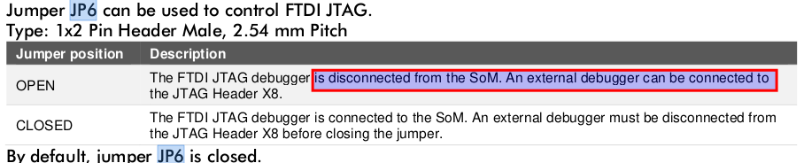
Now I tried using the Dahlia Evaluation Board. I am using 20-10 jtag adapter from Olimex. I leave the jumper JP6 open, if I understood corretly this should be done when an external debugger is used. When running the JLink.exe to test the connection (just running the “connect” command) I get the following output:
Connecting to target via JTAG
InitTarget() start
-- Identifying target device...
-- JTAG selected. Identifying JTAG Chain...
Could not measure total IR len. TDO is constant high.
Error: Scanning JTAG chain failed.
InitTarget() end
Connect failed. Resetting via Reset pin and trying again.
InitTarget() start
-- Identifying target device...
-- JTAG selected. Identifying JTAG Chain...
Could not measure total IR len. TDO is constant high.
Error: Scanning JTAG chain failed.
InitTarget() end
Cannot connect to target.
What I’ve found this similiar topic from '18 and a different carrier board, where the board itself had bad contacts apparently:
Hi @hfranco.tx ,
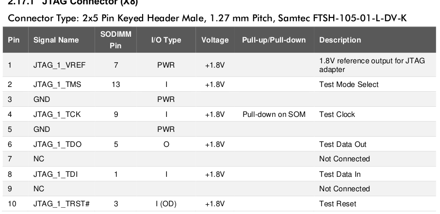
Just checked all the pins, the problem is still there. I wanted to try with some jumper wires as well but the regular jumper cables are too big for the x8 connector. But as you can see from the data sheet of the 20-10 adapter I’m using, the adapter is pretty straight forward, there shouldn’t be any issues there.
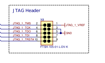
I am no jtag expert, but just checking the voltage on the x8 connector, all these signals
are high. No idea if it should be like that with a jtag debugger disconnected.
Connecting the pins that I mentioned above and it worked as expected. Can you please also share how you’re trying to connect to it on the software side? Are you using JlinkGDBServer?
Hi @hfranco.tx ,
I tried running JLink.exe and JLinkGDBServer.exe as well. I am using the VSCode for debugging and the TDO always high error appears in all of them. And it works completely fine on my custom board. If I find some jumper wires small enough to fit the X8 connector, I can try without the olimex adapter, but I checked its connections, it should be the same as just simple jumper cables.
Hi @hfranco.tx ,
Yes, the correct device is selected. As I said it works completely fine with the custom board and the same settings. From the VSCode and from the JLink directly.
Only thing left to do is to try and bypass the 20-10 adapter.