have you also connected at the same time to X19 - Pins 16 and 17 (UART_2_RTS and UART_2_CTS ) while using the modified binary as per the other thread? Do you see any output?
I connected X19 - Pins 16 and 17 and set the terminal software (TeraTerm) to “Flow control = RTS/CTS”.
X19 - Pins 16 and 17 signal remains low level.
No data is output and it loops at the following location
fsl_uart.c
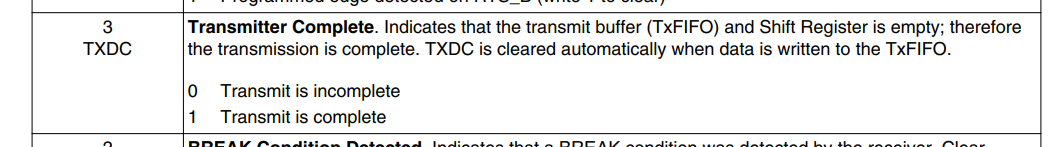
status_t UART_WriteBlocking()…Line:710
while (0U == (base->USR2 & UART_USR2_TXDC_MASK))
UART communication via X1_129/X1_131 is not possible.
I think this may require changing UART2 to Cortex-M4 resource in RDC.
UART communication via X1_137/X1_139 is not possible when the debugger (Computex PALMiCE4) is connected.
UART communication on X1_137/X1_139 works normally without a debugger connected, so it is unclear whether it is a problem with the debugger or the carrier board.
We are in a lot of trouble as the development period is approaching.
Help me.
The JTAG is also connected to the FTDI. Are you using a USB Type C to read the values of the serial console directly from the FTDI?
Should I connect the USB Type C cable to X18 (Debug) or X3 (OTG)?
When connected to X18, the debugger detects a communication error with the CPU and becomes unable to debug. Normally it is not connected to X18.
That could be the key… You should connect it to X18 for UART debug. It looks like your debugger or the program is not compatible with the Dahlia.
Are you plugging your debugger to Dahlia X8? Can you check the connections of the Dahlia (X8) vs the connection from your debugger and see if there are any incompatibilities?
Also, please show the error you are seeing in the debugger. The USB FTDI has 4 channels, including one for the JTAG and 2 for Debug Core A / Debug Core M.
@alvaro.tx
Normally it is connected to a debugger, but X18 is not connected.
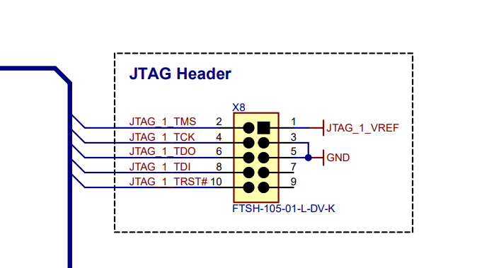
I have attached the JTAG diagram of the debugger.
X8_PIN10(TRST): There is a difference in Debugger_PIN10(/SRST), but other signals are compatible.
Also, this debugger is compatible with the i.MX 8M Mini LPDDR4 EVK (8MMINILPD4-EVK), but the Dahlia carrier board is an untested model.
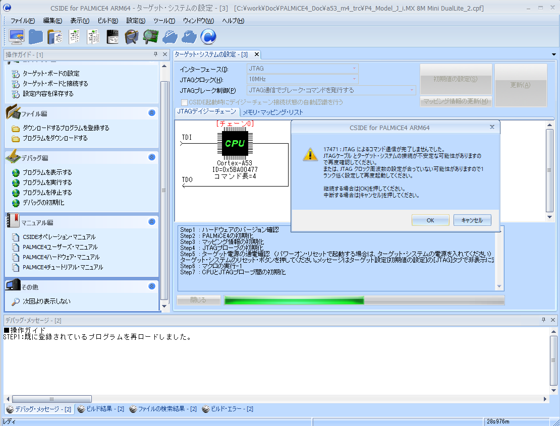
I have attached the error that occurred when connecting X18.
If it’s hard to understand, I’ll send you an enlarged version.
@jorge.tx right is trying to make UART2 work. So far, he succeeded in using UART3 and UART4. Is it possible to use UART3 or 4 instead of UART2? Any reason why you need to use UART2?
We used here another JTAG (JLink Segger) and UART worked just fine. We will check the compared to 8MMINILPD4-EVK. I recommend using just the UART for Debug for now… Any chance you can cover the Debugger_PIN10 and see if that allows the UART to work?
It will require some extra time and our resources are limited now. It seems it is not straightforward like with UART3 and 4. I would recommend using UART2 for Linux and UART4 for FreeRTOS.
Can you disconnect the cable from the JTAG for Pin 10?
Hi @katsu , I’m checking more details on the JTAG and the connection with the i.MX8MM with the Dahlia. Essentially is the same than NXP EVK once you remove the JP6: Direct connection to the SOC.
Can you disconnect the cable from the JTAG for Pin 10?
You can ignore this.
Can you check if you have 1.8V in the JP6_1?
I believe you are trying to debug Core A - Can you try to debug Core M? (MIMX8MM6_M4)
Check with the X1 pin number.
UART1:X1_129/131
UART2:X1_137/139
UART3:X1_147/149 → Cortex-A Debugger
UART4:X1_151/153 → Cortex-M Debugger
Regarding UART2, input and output from Cortex-M4 (FreeRTOS) can be confirmed here.
Regarding UART1, we are currently checking whether the user will use it or not.
Is it correct that the Toradex support team is currently considering the possibility of controlling UART1 from FreeRTOS?
My understanding is to leave JTAG PIN-10 unconnected. I will prepare a cable and try an experiment.
I have prepared a J-LINK debugger, Verdin-Developer-Board, and have attached the results of checking its operation.
It is still in Japanese, but if you have any problems, please contact us. デバッガ動作報告_240212_1.xlsx (1.0 MB)
We published an errata that JTAG was no working OK in V1.0B. This should be fixed in V1.1A.
(HAR-2728)
It could be related to this issue. Any chance you can try in a V1.1A and see if it solves the issue?
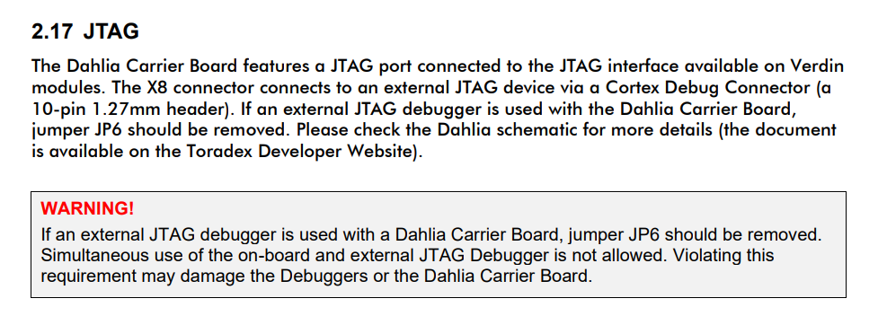
I’m checking your investigation results. Make sure that in Dahlia JP6 is removed when you use a Debugger. Same for all jumpers in X67 in Verdin Development Board.
Thank you for contacting us.
We had a meeting with the user today and received a response that only UART2 can be used with Cortex-M4, so please lower the priority of confirming the use of UART1.
Attached is the output when starting Boot.
Model: Toradex 0060 Verdin iMX8M Mini DualLite 1GB WB IT V1.1C
Carrier: Toradex Dahlia V1.1A, Serial# 10829278
The sticker on the CPU board says V1.1C, so I don’t think there is a corresponding problem, but what do you think?