Colibri + PHY + SFP fiber transceiver

Hello all.

Please we need assitance from Technical Support.

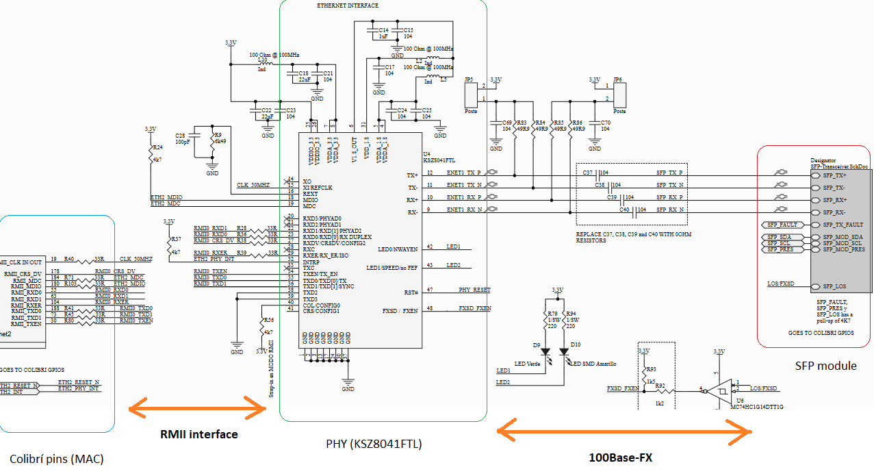
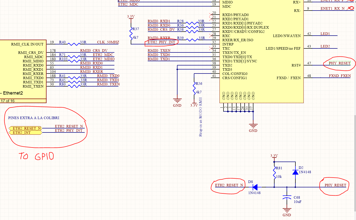
We have a Colibri module (imx6ULL) mounted in a custom carrier board and we want to use the 2nd ethernet interface (eth1) as an optical fiber link. The colibri is connected with an external PHY (in our case, we use the KSZ8041FTL capable of managing up to 100Base-FX) with RMII and MDIO protocols. Then, the PHY goes against an SFP optical transceiver module (in our case, we use the Fiberxon FTM-3401C-SL2G).

Our set up involves the first ethernet interface connected to a switch through an RJ-45 (that is working fine). Then, the second interface has a fibre patch connected to the transceiver, which then connects to a media converter which is connected to the same switch as the first interface.

Info about our SO and image

U-Boot 2020.07-5.7.0-devel+git.1cbeecee44a8 (Jun 27 2022 - 13:27:02 +0000)

CPU: Freescale i.MX6ULL rev1.1 900 MHz (running at 396 MHz)
----------------------------------------------------------------------
TDX X11 5.7.2-devel-20230830152423+build.0 (dunfell) colibri-imx6ull-06487386 ttymxc0
Colibri-iMX6ULL_Reference-Minimal-Image-x11

Our current status is that we managed to have the 2nd ethernet interface detected in Linux (driver assigned upon system start):

DMESG

root@colibri-imx6ull-06487386:~# dmesg | grep eth
[    0.175406] eth_phy: supplied by +V3.3
[    1.502299] fec 20b4000.ethernet eth0: registered PHC device 0
[    2.515431] fec 2188000.ethernet eth1: registered PHC device 1
[   18.212351] Micrel KSZ8041 20b4000.ethernet-1:02: attached PHY driver [Micrel KSZ8041] (mii_bus:phy_addr=20b4000.ethernet-1:02, irq=POLL)
[   18.257811] Micrel KSZ8041 20b4000.ethernet-1:01: attached PHY driver [Micrel KSZ8041] (mii_bus:phy_addr=20b4000.ethernet-1:01, irq=POLL)
[   20.330468] fec 20b4000.ethernet eth0: Link is Up - 100Mbps/Full - flow control rx/tx
[   20.338624] IPv6: ADDRCONF(NETDEV_CHANGE): eth0: link becomes ready

IFCONFIG

root@colibri-imx6ull-06487386:~# ifconfig
eth0      Link encap:Ethernet  HWaddr 00:14:2D:62:FD:5A
          inet addr:192.168.1.66  Bcast:192.168.1.255  Mask:255.255.255.0
          inet6 addr: fe80::214:2dff:fe62:fd5a/64 Scope:Link
          UP BROADCAST RUNNING MULTICAST  MTU:1500  Metric:1
          RX packets:39572 errors:0 dropped:3 overruns:0 frame:0
          TX packets:846 errors:0 dropped:0 overruns:0 carrier:0
          collisions:0 txqueuelen:1000
          RX bytes:3112832 (2.9 MiB)  TX bytes:193140 (188.6 KiB)

eth1      Link encap:Ethernet  HWaddr 00:14:2D:72:FD:5A
          UP BROADCAST MULTICAST  MTU:1500  Metric:1
          RX packets:0 errors:0 dropped:0 overruns:0 frame:0
          TX packets:0 errors:0 dropped:0 overruns:0 carrier:0
          collisions:0 txqueuelen:1000
          RX bytes:0 (0.0 B)  TX bytes:0 (0.0 B)

lo        Link encap:Local Loopback
          inet addr:127.0.0.1  Mask:255.0.0.0
          inet6 addr: ::1/128 Scope:Host
          UP LOOPBACK RUNNING  MTU:65536  Metric:1
          RX packets:12 errors:0 dropped:0 overruns:0 frame:0
          TX packets:12 errors:0 dropped:0 overruns:0 carrier:0
          collisions:0 txqueuelen:1000
          RX bytes:1187 (1.1 KiB)  TX bytes:1187 (1.1 KiB)

ip link show

root@colibri-imx6ull-06487386:~# ip link show
1: lo: <LOOPBACK,UP,LOWER_UP> mtu 65536 qdisc noqueue state UNKNOWN mode DEFAULT group default qlen 1000
    link/loopback 00:00:00:00:00:00 brd 00:00:00:00:00:00
2: eth0: <BROADCAST,MULTICAST,DYNAMIC,UP,LOWER_UP> mtu 1500 qdisc pfifo_fast state UP mode DEFAULT group default qlen 1000
    link/ether 00:14:2d:62:fd:5a brd ff:ff:ff:ff:ff:ff
3: eth1: <NO-CARRIER,BROADCAST,MULTICAST,DYNAMIC,UP> mtu 1500 qdisc pfifo_fast state DOWN mode DEFAULT group default qlen 1000
    link/ether 00:14:2d:72:fd:5a brd ff:ff:ff:ff:ff:ff

networkctl -a

root@colibri-imx6ull-06487386:~# networkctl -a
IDX LINK TYPE     OPERATIONAL SETUP
  1 lo   loopback carrier     unmanaged
  2 eth0 ether    routable    unmanaged
  3 eth1 ether    no-carrier  unmanaged

3 links listed.

and with ethtool we can see that the PHY configuration seems correct:
[ethtool eth1]:

root@colibri-imx6ull-06487386:~# ethtool eth1
Settings for eth1:
        Supported ports: [ FIBRE ]
        Supported link modes:   100baseT/Half 100baseT/Full
        Supported pause frame use: No
        Supports auto-negotiation: No
        Supported FEC modes: Not reported
        Advertised link modes:  100baseT/Half 100baseT/Full
        Advertised pause frame use: No
        Advertised auto-negotiation: No
        Advertised FEC modes: Not reported
        Speed: 100Mb/s
        Duplex: Full
        Port: MII
        PHYAD: 1
        Transceiver: internal
        Auto-negotiation: off
        Supports Wake-on: g
        Wake-on: d
        Link detected: no

Now, regarding the SFP module, we can only read its EEPROM, which has information about the transceiver itself (brand, serial number, model, etc) but that’s it, we are stuck there.

Searching through the internet, we found that linux has a layer called “phylink” that seems to handle this SFP modules dinamically, and we followed some examples in /Documentation/device tree/bindings/net/sff,sfp.txt.

But we are still in the same status. Here in the forum there isn´t much information regarding SFP modules, or even using colibri modules with fiber optics.

Our device tree looks like this:
DEVICE TREE
imx6ull-colibri.dtsi

/ {
...
sfp_eth0: sfp-eth0 {
		compatible = "sff,sfp";
		i2c-bus = <&i2c3>; // this is the bus where the transceiver's eeprom is mapped to
		mod-def0-gpios = <&gpio3 22 GPIO_ACTIVE_LOW>; //MOD-DEF 0 is grounded by the module to indicate that the module is present
		tx-fault-gpios = <&gpio3 21 GPIO_ACTIVE_HIGH>; //Logic 0 indicates normal operation; logic 1 indicates a laser fault of some kind.
	};
}
--------------------------------------------------
&fec2 {
	pinctrl-names = "default", "sleep";
	pinctrl-0 = <&pinctrl_enet2>;
	pinctrl-1 = <&pinctrl_enet2_sleep>;
	phy-mode = "rmii";
	phy-handle = <&ethphy2>;
	phy-supply = <&reg_eth_phy>;
	status = "okay";
	mdio {
		#address-cells = <1>;
		#size-cells = <0>;
		ethphy2: ethernet-phy@2 {
			compatible = "ethernet-phy-ieee802.3-c22";
			max-speed = <100>;
			reg = <2>;
			fsl,mii-bus-wait-delay = <16>; /* 16 usec */
		};
		ethphy1: ethernet-phy@1 {
			compatible = "ethernet-phy-ieee802.3-c22";
			micrel,led-mode = <0>;			
			micrel,fiber-mode;
			sfp = <&sfp_eth0>; // sacado de https://bootlin.com/blog/sfp-modules-on-a-board-running-linux/
			reg = <1>;
			max-speed = <100>;
			fsl,mii-bus-wait-delay = <16>; /* 16 usec */
		};
	};
};

imx6ull-colibri-eval-v3.dtsi

...
&fec1 {
	pinctrl-names = "default", "sleep";
	pinctrl-0 = <&pinctrl_enet1>;
	pinctrl-1 = <&pinctrl_enet1_sleep>;
	phy-mode = "rmii";
	phy-reset-gpios = <&gpio3 2 GPIO_ACTIVE_LOW>;
	interrupt-parent = <&gpio3>;
	interrupts = <10 IRQ_TYPE_LEVEL_HIGH>;
	phy-handle = <&ethphy1>;
	phy-supply = <&reg_eth_phy>;
	status = "okay";
};
------------------------------------
...
&i2c3 {
	status = "okay";
	pinctrl-names = "default", "gpio";
	pinctrl-0 = <&pinctrl_i2c3>;
	pinctrl-1 = <&pinctrl_i2c3_gpio>;
	sda-gpios = <&gpio3 5 (GPIO_ACTIVE_HIGH | GPIO_OPEN_DRAIN)>; // SODIMM 76
	scl-gpios = <&gpio3 6 (GPIO_ACTIVE_HIGH | GPIO_OPEN_DRAIN)>; // SODIMM 70

	eepromphy: at24c01a@50 {
		compatible = "atmel,24c01";
		pagesize = <8>;
		reg = <0x50>;
	};
};
  1. Is our device tree coherent or has something wrong?
  2. Are there any examples of how we should set the device tree in order to see the SFP module?
  3. How does the SFP module tells the PHY or the CPU that the link is UP or DOWN? Who controls that?

I attached the schematics of the Colibri-to-PHY, and the PHY-to-SFP transceiver.
Colibri-PHY.pdf (210.4 KB)

We want to know at least where to look for answers, if it might be hardware/pcb_routing or software because we are a bit lost here.

Hope a soon response.

Best regards,
Martin

Hi @martin_mig,

I guess you are using the SMII of the KSZ8041FTL, correct?
If so, are you sure that the TX/RX lines on that specific PHY do not require any pull-up resistors? I have seen such on many design examples.

Hi vmetodiev,

No, we aren´t using SMII.
Our imx6ull colibri module’s 2nd ethernet interface only supports MII and RMII. Because of the lower pin count, we are using the RMII interface between our module and the PHY.

Though, in the SFP transceiver datasheet, we are not sure about what it means when it points out that the transceiver supports SGMII and that has a built-in PHY.

Regarding the pull-up resistors in TX/RX lines, we are following KSZ8041FTL datasheet recommendations.

If you have any design examples of the connection between PHY KSZ8041FTL and an SFP Transceiver, we will appreciate if you share them.

Thanks in advanced.

Hi @martin_mig ,

Let’s agree on the point than whenever a PHYter is used for conversion between two different standards, we normally have two sides - the media independent side and the media dependent side.

Normally, the media independent side is the link between the processor and the PHYter IC. It is clear from your explanations that you had two options (MII and RMII), and you have decided to go with the RMII.

Now, what is still not quite clear to me is what you have done with the media dependent side - the one that interfaces the PHYter and the SFP connector. Normally, there are two options - SGMII or 1000BASE-X.

In this regard, my next questions are:

  1. Which technology have you decided to use between the PHYter and the SFP?
    I expect it is SGMII/SMII (from what I remember from the KSZ8041FTL datasheet)…
  2. Do you have any reference schematics for it?

Unfortunately, I do not have anything related to PHY KSZ8041FTL. At the moment I am also developing a design with SFP, but with an IC from Realtek.

ADDENDUM:

This is the project I am currently using to copy-paste from.
https://pro.lceda.cn/editor#id=94361946b2d945bab578036685376c08,tab=*bd8e4cb9a9434b5080db41445188eb87
However, it is still unclear to me why an RLT8213B is used, while the RTL8367S provides SGMII as well. And what I am doing is to expose the SGMII from the IC to the SFP connector.

I also forgot to mention the Alaska family by Marvell (it comes with some good documentation):

*Note about my previous post: I have mentioned SGMII/SMII as “media dependent”, which is a bit confusing… In fact, it is still media independent interface towards the SFP and the actual media converter IC inside the SFP transceiver.

But still, the my question to you remains the same, namely what is your complete schematic between the PHY and the SFP…

Hi vmetodiev,

Thanks for the quick response.

I hope the next image clarifies what was our intention:

In our design, the media dependent side of the KSZ8041FTL PHY (mounted in our host board) was intented to be 100Base-FX through the pins TX+/- and RX+/-. So, the SFP should be 100Base-FX capable. So far, nothing extrange.

But, thanks to your questions and after doing a further research, we found out that not all SFP modules are the same, despite all of them having the same MSA-SFP 20 pins interface.
For example, we didin’t know that some SFP modules could have a PHY inside, like for example the module we bought (Fiberxon FTM-3401C-SL2G). And that changes everything, because an SFP module which has a PHY inside has a compatible media independent interface in its 20 pin interface (like SGMII or other). On the other hand, if the SFP module doesn’t have a PHY inside, then its pins are media dependent, like 100Base-FX. At least, thats what we understood after all the research we made.

So, going back to our design, I think the problem is that we were trying to connect an SFP module which has a PHY inside and a SGMII interface with another PHY (in our board) which is compatible with 100Base-FX.
We already ordered another SFP module which doesn’t have a PHY inside, which we took from an application note from AVAGO (Application Note 5582).
I think the thing that confused us was the fact that the SFP modules has all the same pin count interface (20), but it can be connected to different things, it can be an SGMII interface, or a 100Base-FX, depending on what’s inside of it.

Please, if you have deep knowledge of this topic, we will appreciate if your share it with us. We are still learning about PHYs, fiber optics, and so on.

Best regards,
Martin

Hello @martin_mig ,

I read the entire topic and also suspect that the issue is related to your SFP having a PHY inside.

Please let us know of the results when the new SFP arrives.

Also, let us know if you have any other doubts.

Best regards,
Daniel Morais

Hi @daniel_m.tx

The new transceiver has arrived (the AFBR-57E6APZ from AVAGO), and I can confirm it doesn’t have a PHY inside of it.

At first, it didn’t work. But, after a few days struggling we managed to make it work.
Apparently, the issue was related with some device tree definitions.

As you can see in the image above (schematics of our custom board), the KSZ8041FTL has two signals that goes straight to the imx6ull and we treated them like GPIOS.
One of them is the ETH2_RESET_N (that goes to the reset circuit first and then into the PHY_RESET pin), and the other one was the interrupt signal ETH2_PHY_INT that goes directly into the PHY.

Reading from several posts, and with the help of the documentation, we tried to define those signals in the device tree as follows:

Device tree wrong:

...
&fec1 {
	pinctrl-names = "default", "sleep";
	pinctrl-0 = <&pinctrl_enet1>;
	pinctrl-1 = <&pinctrl_enet1_sleep>;
	phy-mode = "rmii";
	phy-reset-gpios = <&gpio3 2 GPIO_ACTIVE_LOW>;
	interrupt-parent = <&gpio3>;
	interrupts = <10 IRQ_TYPE_LEVEL_HIGH>;
	phy-handle = <&ethphy1>;
	phy-supply = <&reg_eth_phy>;
	status = "okay";
};
...
		pinctrl_enet1: enet1-grp {
			fsl,pins = <
				MX6UL_PAD_ENET1_RX_DATA0__ENET1_RDATA00	0x1b0b0
				MX6UL_PAD_ENET1_RX_DATA1__ENET1_RDATA01	0x1b0b0
				MX6UL_PAD_ENET1_RX_EN__ENET1_RX_EN		0x1b0b0
				MX6UL_PAD_ENET1_RX_ER__ENET1_RX_ER		0x1b0b0
				MX6UL_PAD_GPIO1_IO04__ENET1_REF_CLK1	0x4001b031
				MX6UL_PAD_ENET1_TX_DATA0__ENET1_TDATA00	0x1b0b0
				MX6UL_PAD_ENET1_TX_DATA1__ENET1_TDATA01	0x1b0b0
				MX6UL_PAD_ENET1_TX_EN__ENET1_TX_EN 		0x1b0b0
				//Reset PHY
				MX6UL_PAD_LCD_HSYNC__GPIO3_IO02		0xb0
				//Interrupt
				MX6UL_PAD_LCD_DATA05__GPIO3_IO10	0xb0
				// TX Fault
				MX6UL_PAD_LCD_DATA16__GPIO3_IO21	0x2000
				// MOD PRES
				MX6UL_PAD_LCD_DATA17__GPIO3_IO22	0x2000
			>;
		};

The shymptons with the wrong device tree were:

  • An exception log at system start-up related to some ignored interrupt
[    2.131690] irq 140: nobody cared (try booting with the "irqpoll" option)
[    2.138537] CPU: 0 PID: 1 Comm: swapper/0 Not tainted 5.4.193-5.7.2-devel+git.b60d3160fd04 #1
[    2.147109] Hardware name: Freescale i.MX6 Ultralite (Device Tree)
[    2.153370] [<8010ec98>] (unwind_backtrace) from [<8010bc04>] (show_stack+0x10/0x14)
[    2.161184] [<8010bc04>] (show_stack) from [<8091af98>] (dump_stack+0x90/0xa4)
[    2.168469] [<8091af98>] (dump_stack) from [<809128a4>] (__report_bad_irq+0x3c/0xc0)
[    2.176276] [<809128a4>] (__report_bad_irq) from [<8016ed94>] (note_interrupt+0x264/0x2b0)
[    2.184606] [<8016ed94>] (note_interrupt) from [<8016ba1c>] (handle_irq_event_percpu+0x58/0x64)
[    2.193365] [<8016ba1c>] (handle_irq_event_percpu) from [<8016ba6c>] (handle_irq_event+0x44/0x68)
[    2.202300] [<8016ba6c>] (handle_irq_event) from [<8016f7dc>] (handle_level_irq+0xb4/0x140)
[    2.210712] [<8016f7dc>] (handle_level_irq) from [<8016ab48>] (generic_handle_irq+0x24/0x34)
[    2.219212] [<8016ab48>] (generic_handle_irq) from [<8051c4b0>] (mxc_gpio_irq_handler+0x48/0x164)
[    2.228149] [<8051c4b0>] (mxc_gpio_irq_handler) from [<8051d0b0>] (mx3_gpio_irq_handler+0x60/0xac)
[    2.237166] [<8051d0b0>] (mx3_gpio_irq_handler) from [<8016ab48>] (generic_handle_irq+0x24/0x34)
[    2.246009] [<8016ab48>] (generic_handle_irq) from [<8016b160>] (__handle_domain_irq+0x5c/0xb0)
[    2.254769] [<8016b160>] (__handle_domain_irq) from [<8050a5c8>] (gic_handle_irq+0x4c/0x90)
[    2.263183] [<8050a5c8>] (gic_handle_irq) from [<80101b0c>] (__irq_svc+0x6c/0x90)
[    2.270707] Exception stack(0x9404fc00 to 0x9404fc48)
[    2.275801] fc00: 00200140 80e5fc80 00000000 16d35000 00000202 00000000 00000000 00000001
[    2.284032] fc20: 9404e000 9404fce8 9404fc50 94057000 e214a699 9404fc50 80129454 80102280
[    2.292248] fc40: 60000113 ffffffff
[    2.295784] [<80101b0c>] (__irq_svc) from [<80102280>] (__do_softirq+0x98/0x278)
[    2.303243] [<80102280>] (__do_softirq) from [<80129454>] (irq_exit+0xb0/0xd8)
[    2.310527] [<80129454>] (irq_exit) from [<8016b164>] (__handle_domain_irq+0x60/0xb0)
[    2.318416] [<8016b164>] (__handle_domain_irq) from [<8050a5c8>] (gic_handle_irq+0x4c/0x90)
[    2.326825] [<8050a5c8>] (gic_handle_irq) from [<80101b0c>] (__irq_svc+0x6c/0x90)
[    2.334346] Exception stack(0x9404fce8 to 0x9404fd30)
[    2.339436] fce0:                   941f3a68 60000013 00000004 00000006 941f3a00 00000000
[    2.347667] fd00: 94511b40 0000008c 60000013 941f3ad0 941f3a68 94057000 02032204 9404fd38
[    2.355888] fd20: 8016da60 809204d4 60000013 ffffffff
[    2.360988] [<80101b0c>] (__irq_svc) from [<809204d4>] (_raw_spin_unlock_irqrestore+0x1c/0x20)
[    2.369664] [<809204d4>] (_raw_spin_unlock_irqrestore) from [<8016da60>] (__setup_irq+0x35c/0x79c)
[    2.378685] [<8016da60>] (__setup_irq) from [<8016e000>] (request_threaded_irq+0xd0/0x148)
[    2.387006] [<8016e000>] (request_threaded_irq) from [<80170af4>] (devm_request_threaded_irq+0x64/0xb8)
[    2.396465] [<80170af4>] (devm_request_threaded_irq) from [<80617b24>] (fec_probe+0xe04/0x13b4)
[    2.405230] [<80617b24>] (fec_probe) from [<805927dc>] (platform_drv_probe+0x48/0x98)
[    2.413126] [<805927dc>] (platform_drv_probe) from [<805906b8>] (really_probe+0x24c/0x488)
[    2.421455] [<805906b8>] (really_probe) from [<80590abc>] (driver_probe_device+0x78/0x1c4)
[    2.429782] [<80590abc>] (driver_probe_device) from [<80590e68>] (device_driver_attach+0x58/0x60)
[    2.438715] [<80590e68>] (device_driver_attach) from [<80590f24>] (__driver_attach+0xb4/0x154)
[    2.447389] [<80590f24>] (__driver_attach) from [<8058e840>] (bus_for_each_dev+0x64/0x90)
[    2.455627] [<8058e840>] (bus_for_each_dev) from [<8058f880>] (bus_add_driver+0x16c/0x208)
[    2.463948] [<8058f880>] (bus_add_driver) from [<8059179c>] (driver_register+0x74/0x108)
[    2.472094] [<8059179c>] (driver_register) from [<801026f0>] (do_one_initcall+0x44/0x194)
[    2.480334] [<801026f0>] (do_one_initcall) from [<80e01010>] (kernel_init_freeable+0x148/0x1e4)
[    2.489096] [<80e01010>] (kernel_init_freeable) from [<8091b144>] (kernel_init+0x8/0x110)
[    2.497333] [<8091b144>] (kernel_init) from [<801010e8>] (ret_from_fork+0x14/0x2c)
[    2.504941] Exception stack(0x9404ffb0 to 0x9404fff8)
[    2.510025] ffa0:                                     00000000 00000000 00000000 00000000
[    2.518252] ffc0: 00000000 00000000 00000000 00000000 00000000 00000000 00000000 00000000
[    2.526476] ffe0: 00000000 00000000 00000000 00000000 00000013 00000000
[    2.533118] handlers:
[    2.535422] [<(ptrval)>] fec_enet_interrupt
[    2.539633] Disabling IRQ #140
[    2.545064] fec 2188000.ethernet eth1: registered PHC device 1

  • A few minutes following the start-up there was another exception showing an stack trace and a TX_RING_DUMP message from the fec1.
root@colibri-imx6ull-06487386:~# [ 1742.073353] ------------[ cut here ]------------
[ 1742.078220] WARNING: CPU: 0 PID: 0 at net/sched/sch_generic.c:479 dev_watchdog+0x29c/0x2a0
[ 1742.086584] NETDEV WATCHDOG: eth1 (fec): transmit queue 0 timed out
[ 1742.092914] Modules linked in: bluetooth imx_sdma virt_dma secvio libcomposite
[ 1742.100283] CPU: 0 PID: 0 Comm: swapper/0 Not tainted 5.4.193-5.7.2-devel+git.b60d3160fd04 #1
[ 1742.108880] Hardware name: Freescale i.MX6 Ultralite (Device Tree)
[ 1742.115184] [<8010ec98>] (unwind_backtrace) from [<8010bc04>] (show_stack+0x10/0x14)
[ 1742.123046] [<8010bc04>] (show_stack) from [<8091af98>] (dump_stack+0x90/0xa4)
[ 1742.130381] [<8091af98>] (dump_stack) from [<809121dc>] (__warn+0xbc/0xd8)
[ 1742.137364] [<809121dc>] (__warn) from [<8091227c>] (warn_slowpath_fmt+0x84/0x98)
[ 1742.144957] [<8091227c>] (warn_slowpath_fmt) from [<807cc8e0>] (dev_watchdog+0x29c/0x2a0)
[ 1742.153252] [<807cc8e0>] (dev_watchdog) from [<80180be8>] (call_timer_fn.constprop.0+0x24/0x98)
[ 1742.162084] [<80180be8>] (call_timer_fn.constprop.0) from [<801812ec>] (run_timer_softirq+0x44c/0x460)
[ 1742.171527] [<801812ec>] (run_timer_softirq) from [<801022ec>] (__do_softirq+0x104/0x278)
[ 1742.179831] [<801022ec>] (__do_softirq) from [<80129454>] (irq_exit+0xb0/0xd8)
[ 1742.187180] [<80129454>] (irq_exit) from [<8016b164>] (__handle_domain_irq+0x60/0xb0)
[ 1742.195142] [<8016b164>] (__handle_domain_irq) from [<8050a5c8>] (gic_handle_irq+0x4c/0x90)
[ 1742.203619] [<8050a5c8>] (gic_handle_irq) from [<80101b0c>] (__irq_svc+0x6c/0x90)
[ 1742.211197] Exception stack(0x80f01ef0 to 0x80f01f38)
[ 1742.216328] 1ee0:                                     00000000 00000195 16d35000 97b950c0
[ 1742.224620] 1f00: 80f0bb84 00000001 97b944b8 9ba82121 9a86ec2f 00000195 00000195 00000000
[ 1742.232900] 1f20: fffffff5 80f01f40 806b7abc 806b7ac0 a0010013 ffffffff
[ 1742.239628] [<80101b0c>] (__irq_svc) from [<806b7ac0>] (cpuidle_enter_state+0x80/0x3a0)
[ 1742.247766] [<806b7ac0>] (cpuidle_enter_state) from [<806b7e1c>] (cpuidle_enter+0x28/0x38)
[ 1742.256164] [<806b7e1c>] (cpuidle_enter) from [<8014d718>] (do_idle+0x1c4/0x26c)
[ 1742.263683] [<8014d718>] (do_idle) from [<8014da50>] (cpu_startup_entry+0x18/0x1c)
[ 1742.271376] [<8014da50>] (cpu_startup_entry) from [<80e00eb0>] (start_kernel+0x3cc/0x3e4)
[ 1742.279753] ---[ end trace 9d07ea583e60f395 ]---
[ 1742.284492] fec 2188000.ethernet eth1: TX ring dump
[ 1742.289448] Nr     SC     addr       len  SKB
[ 1742.293901]   0    0x1c00 0x95018800   90 91133828
[ 1742.298779]   1    0x1c00 0x95019000   54 ebcf9d93
[ 1742.303658]   2    0x1c00 0x95019800  110 2e9c2280
[ 1742.308531]   3    0x1c00 0x9501a000  269 e764d713
[ 1742.313406]   4    0x1c00 0x9501a800  163 c72d3589
[ 1742.318279]   5    0x1c00 0x9501b000   86 09323a72
... and this continues until Nr 511.
  • The interfaces weren’t working correctly (ping was ok for both interfaces but there was no TX/RX packets count for the second interface using the command ifconfig).

So, seeing that the problem seemed to be related with some interrupt, we tried to remove everything that was related to the fec1 and the interrupt, so we came up with this device tree:

Device tree good:

&fec1 {
	pinctrl-names = "default", "sleep";
	pinctrl-0 = <&pinctrl_enet1>;
	pinctrl-1 = <&pinctrl_enet1_sleep>;
	phy-mode = "rmii";
	phy-reset-gpios = <&gpio3 2 GPIO_ACTIVE_LOW>;
	phy-handle = <&ethphy1>;
	phy-supply = <&reg_eth_phy>;
	status = "okay";
};

		pinctrl_enet1: enet1-grp {
			fsl,pins = <
				MX6UL_PAD_ENET1_RX_DATA0__ENET1_RDATA00	0x1b0b0
				MX6UL_PAD_ENET1_RX_DATA1__ENET1_RDATA01	0x1b0b0
				MX6UL_PAD_ENET1_RX_EN__ENET1_RX_EN		0x1b0b0
				MX6UL_PAD_ENET1_RX_ER__ENET1_RX_ER		0x1b0b0
				MX6UL_PAD_GPIO1_IO04__ENET1_REF_CLK1	0x4001b031
				MX6UL_PAD_ENET1_TX_DATA0__ENET1_TDATA00	0x1b0b0
				MX6UL_PAD_ENET1_TX_DATA1__ENET1_TDATA01	0x1b0b0
				MX6UL_PAD_ENET1_TX_EN__ENET1_TX_EN 		0x1b0b0
				//Reset PHY
				MX6UL_PAD_LCD_HSYNC__GPIO3_IO02			0xb0
				// MOD PRES
				MX6UL_PAD_LCD_DATA17__GPIO3_IO22		0x2000
			>;
		};

As soon as we removed the interrupt related signals from the device tree and tried again, the interfaces started working well.

So, now the questions.

  1. If we want to define and use the interrupt signal, how the device tree should look like? Keep in mind that the interrupt signal is connected to pin 68 of the SODIMM which, according to the datasheet, is the GPIO3 10 pin.

  2. Also, we are having trouble entering Toradex device tree customization for the imx6ull web page. We want to see the meaning of each bit of the value assigned to each pin (like 0x1b0b0 or 0x2000), but the page seems to be down.

Looking forward a soon response.

Best regards,
Martin

Hello @martin_mig,

Thank you for the update regarding this issue!

I’d like to address your questions:

1 - The configuration you’ve applied appears to be correct. Given that the PHY is functioning well without the interrupt pin, it’s possible that this functionality is not required. However, I couldn’t find specific information in the datasheet to confirm this. Another possibility is that the driver for this PHY may not have the necessary functions to handle the interrupt signal.

2 - The detailed meanings of each bit can be found in Table 4-2 of the iMX6ULL Datasheet under the “Pad Control Register.” I didn’t encounter any issues when accessing this information today, so it might be a problem on your end. I recommend trying again when it’s convenient for you.

Best regards,
Daniel Morais