Colibri IMX8X ADV7280 device tree

Hello,

I’m working on a custom carrier board housing a Colibri iMX8DX 1GB WB module. The end goal is to get an analog camera working using the ADV7280 through the parallel CSI interface (not MIPI CSI-2).
I couldn’t find an example for that particular usage (iMX8X + ADV7280).

Those are the relevant parts of the device tree:

&i2c1 {
    clock-frequency = <100000>;
    status = "okay";

    adv_7280: adv7280@20 {
        compatible = "adi,adv7280";
        reg = <0x20>;
        pinctrl-names = "default";
        pinctrl-0 = <&pinctrl_parallel_csi>;

        reset-gpios = <&lsio_gpio3 12 GPIO_ACTIVE_LOW>; // SODIMM_71
        powerdown-gpios = <&lsio_gpio3 21 GPIO_ACTIVE_LOW>; // SODIMM_98
        // csi_id = <0>;
        mclk = <27000000>;
        status = "okay";

        port {
            adv7280_ep: endpoint@3 {
                reg = <3>; // AIN4
                remote-endpoint = <&parallel_csi_ep>; // Link to parallel csi endpoint
                bus-type = <5>; // Parallel
                bus-width = <8>; // 8-bit
                data-shift = <2>; // D2-D9 are used
                vsync-active = <1>;
				hsync-active = <1>;
				pclk-sample = <1>;
            };
        };
    };
};

&mipi_csi_0 {
    status = "disabled";
};

&cameradev {
	parallel_csi;
	status = "okay";
};

&isi_1 {
    interface = <6 0 2>;
    status = "okay";

    cap_device {
        status = "okay";
    };
};

&parallel_csi {
    #address-cells = <1>;
	#size-cells = <0>;
    status = "okay";

    port@0 {
        reg = <0>;
        parallel_csi_ep: endpoint {
            remote-endpoint = <&adv7280_ep>; // Link to adv7280 endpoint
        };
    };
};

&iomuxc {
    pinctrl-names = "default";
    pinctrl-0 = <&pinctrl_newhog0>, <&pinctrl_hog1>,
                <&pinctrl_lcd>, <&pinctrl_keepalive>;

    pinctrl_keepalive: keepalive_pingrp {
        fsl,pins = 
            <IMX8QXP_SPDIF0_EXT_CLK_LSIO_GPIO0_IO12 0x46000061>; /* Keep_alive: output */
    };

    pinctrl_lcd: lcd_pingrp {
        fsl,pins = 
            <IMX8QXP_ESAI0_FSR_ADMA_LCDIF_D00            0x00000060>, /* LCD_BL: input */
            <IMX8QXP_USDHC1_WP_LSIO_GPIO4_IO21           0x46000061>; /* LCD_BL: output */
    };

    pinctrl_newhog0: newhog0grp {
        fsl,pins =
            <IMX8QXP_QSPI0A_DATA2_LSIO_GPIO3_IO11    0x20>,       /* SODIMM  69 */
            <IMX8QXP_SAI0_TXC_LSIO_GPIO0_IO26        0x20>,       /* SODIMM  79 */
            <IMX8QXP_ENET0_RGMII_RXC_LSIO_GPIO5_IO03 0x06000020>, /* SODIMM  85 */
            <IMX8QXP_QSPI0B_SCLK_LSIO_GPIO3_IO17     0x20>,       /* SODIMM  95 */
            <IMX8QXP_SAI0_RXD_LSIO_GPIO0_IO27        0x20>,       /* SODIMM  97 */
            <IMX8QXP_QSPI0B_DATA0_LSIO_GPIO3_IO18    0x20>,       /* SODIMM  99 */
            <IMX8QXP_SAI0_TXFS_LSIO_GPIO0_IO28       0x20>,       /* SODIMM 101 */
            <IMX8QXP_SAI0_TXD_LSIO_GPIO0_IO25        0x20>,       /* SODIMM 103 */
            <IMX8QXP_QSPI0B_DATA1_LSIO_GPIO3_IO19    0x20>,       /* SODIMM 105 */
            <IMX8QXP_USB_SS3_TC2_LSIO_GPIO4_IO05     0x20>,       /* SODIMM 127 */
            <IMX8QXP_USB_SS3_TC3_LSIO_GPIO4_IO06     0x20>,       /* SODIMM 131 */
            <IMX8QXP_USB_SS3_TC1_LSIO_GPIO4_IO04     0x20>,       /* SODIMM 133 */
            <IMX8QXP_SAI1_RXFS_LSIO_GPIO0_IO31       0x20>,       /* SODIMM 100 */
            <IMX8QXP_QSPI0B_DQS_LSIO_GPIO3_IO22      0x20>,       /* SODIMM 102 */
            <IMX8QXP_QSPI0B_SS0_B_LSIO_GPIO3_IO23    0x20>;       /* SODIMM 104 */
    };

    // ADV7280 parallel video interface
    pinctrl_parallel_csi: parallelcsigrp {
        fsl,pins =
            <IMX8QXP_CSI_D00_CI_PI_D02            0xC0000041>,
            <IMX8QXP_CSI_D01_CI_PI_D03            0xC0000041>,
            <IMX8QXP_CSI_D02_CI_PI_D04            0xC0000041>,
            <IMX8QXP_CSI_D03_CI_PI_D05            0xC0000041>,
            <IMX8QXP_CSI_D04_CI_PI_D06            0xC0000041>,
            <IMX8QXP_CSI_D05_CI_PI_D07            0xC0000041>,
            <IMX8QXP_CSI_D06_CI_PI_D08            0xC0000041>,
            <IMX8QXP_CSI_D07_CI_PI_D09            0xC0000041>,
            <IMX8QXP_CSI_PCLK_CI_PI_PCLK          0xC0000041>,
            <IMX8QXP_CSI_HSYNC_CI_PI_HSYNC        0xC0000041>,
            <IMX8QXP_CSI_VSYNC_CI_PI_VSYNC        0xC0000041>,
            <IMX8QXP_CSI_MCLK_CI_PI_MCLK          0xC0000041>,
            <IMX8QXP_QSPI0A_DATA3_LSIO_GPIO3_IO12 0xC6000041>, // SODIMM 98
            <IMX8QXP_QSPI0B_DATA3_LSIO_GPIO3_IO21 0xC6000041>; // SODIMM 71
    };
};

pinctrl_hog2 was removed from pinctrl-0 in iomuxc because SODIMM_75 was in conflict.

Here’s what I’ve got so far:

  • I compiled the ADV7180 driver. It’s loaded and it found the chip via i2c.
    dmesg | grep adv7 gives
    adv7180 1-0020: chip id 0x43 found @ 0x20 (5a810000.i2c)
  • Something related to the image sensor interface is also working, but then there’s a problem:
[    1.463013] mxc-isi 58110000.isi: mxc_isi.1 registered successfully
[    1.569492] mxc-parallel-csi 58261000.pcsi: mxc_parallel_csi_probe probe successfully
[   10.507140] imx8_media_dev: module is from the staging directory, the quality is unknown, you have been warned.
[   10.540520] mx8-img-md: Registered mxc_isi.1.capture as /dev/video2
[   10.570707] unregister ISI channel: mxc_isi.1
[   10.826565] mxc-jpeg 58400000.jpegdec: decoder device registered as /dev/video2 (81,2)

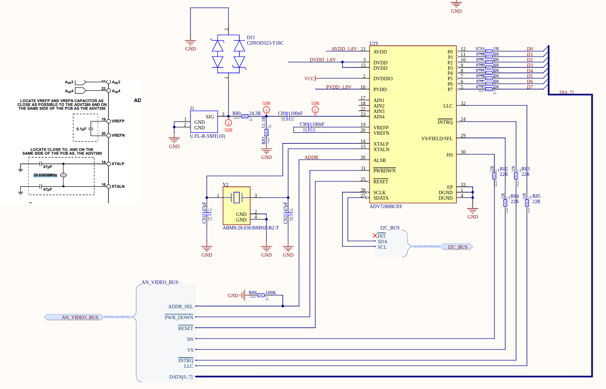
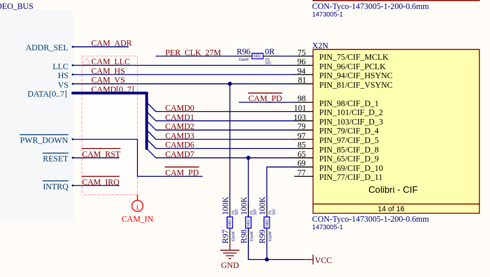
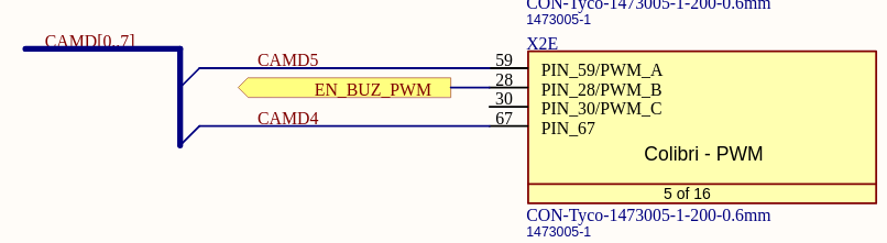
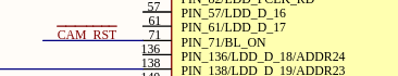
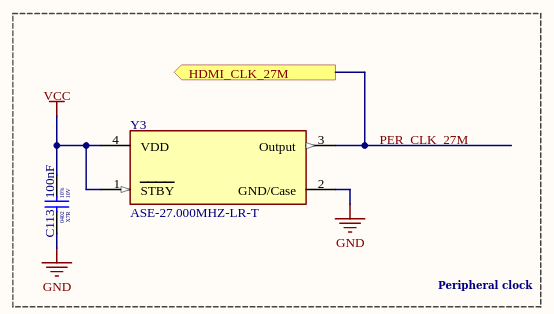
Here are are the relevant parts of the schematic:

ADV7280 side:

SoM side:

image

image

As far as I understand, the video device gets created but it is later overwritten by mxc-jpeg.
I assume there’s something missing or misconfigured in the device tree.

What can I do to get the video device working?

Thank you in advance for any help provided.

Hardware info:
Custom board
SoM: Colibri iMX8DX 1GB WB
OS: Custom based on torizon-core-docker-colibri-imx8x-Tezi_6.3.0+build.4
Kernel version: Linux 5.15.77-6.3.0+git.ddc6ca4d76ea
Full dmesg log: dmesg.txt (30.0 KB)

Hi @c.azais ,

Taking a quick look at your Device Tree I don’t see any obvious errors here. In fact, it doesn’t look like it’s a issue related to Device Tree nor hardware, as the driver was able to find your device.

Looking online I found out a similar problem as yours if the imx8_media_dev module from NXP is loaded before your camera module:

Maybe that’s the case, given that in your dmesg logs the adv7180 driver prints a message later into the boot?

To mitigate this, you can try to compile the camera driver as a kernel built-in instead of a module, as it will load earlier.

Best regards,
Lucas Akira

Hi @lucas_a.tx ,

Thank you for your quick response.
It was indeed a problem with module loading order. I was able to change the module loading order by adding a softdep to /etc/modprobe.d:

sudo bash -c "echo softdep imx8_media_dev pre: adv7180 > /etc/modprobe.d/adv7180.conf"

And this fixed the problem on further boots.

I am now faced with a new problem now that the module order is fixed:

[   10.878860] adv7180 1-0020: chip id 0x43 found @ 0x20 (5a810000.i2c)
[   10.891973] imx8_media_dev: module is from the staging directory, the quality is unknown, you have been warned.
[   10.892722] imx8_media_dev: module is from the staging directory, the quality is unknown, you have been warned.
[   10.931703] mx8-img-md: Registered mxc_isi.1.capture as /dev/video2
[   10.931917] mx8-img-md: Registered sensor subdevice: adv7180 1-0020 (1)
[   10.931935] mx8-img-md: created link [mxc_isi.1] => [mxc_isi.1.capture]
[   10.931945] mx8-img-md: created link [mxc-parallel-csi] => [mxc_isi.1]
[   10.931954] mx8-img-md: subdev_notifier_complete error exit
[   10.931997] mxc-md bus@58000000:camera: Sensor register failed
[   10.932007] mxc-md: probe of bus@58000000:camera failed with error -515
[   11.050371] mxc-jpeg 58400000.jpegdec: decoder device registered as /dev/video3 (81,3)
[   11.069046] mxc-jpeg 58450000.jpegenc: encoder device registered as /dev/video4 (81,4)
[   11.297025] fec 5b040000.ethernet ethernet0: renamed from eth0
[   11.419178] Micrel KSZ8041 5b040000.ethernet-1:02: attached PHY driver (mii_bus:phy_addr=5b040000.ethernet-1:02, irq=POLL)
[   12.898977] mxc-parallel-csi: is_entity_link_setup, No remote pad found!

I’m going to try a few modifications with the device tree since I assume the “remote pad” has something to do with the remote-endpoint entities in the port.

Update:
When I run the following command:

gst-launch-1.0 v4l2src device=/dev/video2 ! video/x-raw,width=640,height=480 ! fakesink sync=false

This is the output:

Setting pipeline to PAUSED ...
Pipeline is live and does not need PREROLL ...
Pipeline is PREROLLED ...
Setting pipeline to PLAYING ...
New clock: GstSystemClock
ERROR: from element /GstPipeline:pipeline0/GstV4l2Src:v4l2src0: Failed to allocate required memory.
Additional debug info:
../sys/v4l2/gstv4l2src.c(976): gst_v4l2src_decide_allocation (): /GstPipeline:pipeline0/GstV4l2Src:v4l2src0:
Buffer pool activation failed
Execution ended after 0:00:00.020423353
Setting pipeline to NULL ...
Freeing pipeline ...

And this is the output in dmesg:

[  285.573065] mxc-parallel-csi: is_entity_link_setup, No remote pad found!
[  285.586633] mxc-parallel-csi: is_entity_link_setup, No remote pad found!
[  285.589351] mxc-parallel-csi: mxc_pcsi_enum_framesizes, No remote pad found!
[  285.589576] mxc-parallel-csi: mxc_pcsi_enum_framesizes, No remote pad found!
[  285.589691] mxc-parallel-csi: mxc_pcsi_enum_framesizes, No remote pad found!
[  285.589794] mxc-parallel-csi: mxc_pcsi_enum_framesizes, No remote pad found!
[  285.589904] mxc-parallel-csi: mxc_pcsi_enum_framesizes, No remote pad found!
[  285.590009] mxc-parallel-csi: mxc_pcsi_enum_framesizes, No remote pad found!
[  285.590118] mxc-parallel-csi: mxc_pcsi_enum_framesizes, No remote pad found!
[  285.590221] mxc-parallel-csi: mxc_pcsi_enum_framesizes, No remote pad found!
[  285.593853] mxc-parallel-csi: mxc_pcsi_g_frame_interval, No remote pad found!
[  285.609051] mxc-parallel-csi: mxc_pcsi_s_power, No remote pad found!
[  285.609110] mxc_isi.1: Call subdev s_power fail!

I think I am missing some properties on the adv_7280 node of the device tree, especially:

  • clocks
  • clock-names
  • mclk_source
  • parallel_csi ?

How do I configure the clocks property, considering the clock is just an external crystal?

Kind regards,
Corentin.

Hi @c.azais ,

Glad I was able to help with your first issue.

I think I am missing some properties on the adv_7280 node of the device tree

Looking at the device tree bindings documentation for this driver, I don’t think these properties are strictly necessary.

I don’t know very much about the specifics of the ADV7280 driver nor on on NXP drivers related to image capture, but from the logs you shared I assume the endpoint is being found and linked before the error messages:

[   10.931945] mx8-img-md: created link [mxc-parallel-csi] => [mxc_isi.1]

With the information we have, it’s hard to know for sure exactly what is causing the issue.

Even though it’s using MIPI-CSI2, maybe the solution from the link below helps with the general structure on how things should be on the device tree:

From the link above apparently the cause of the No remote pad found! errors is related to the adv7180.c driver itself.

Best regards,
Lucas Akira

Hello again @lucas_a.tx ,

Thanks you very much for your help. I was able to remove that No remote pad found error.

I’m now able to capture pictures with gstreamer. This is the command i’m using:

gst-launch-1.0 v4l2src device=/dev/video2 num-buffers=1 ! "video/x-raw,width=320,height=240" ! jpegenc ! filesink location=/tmp/test.jpg

The problem now is that the pictures i’m getting are completely wrong and fixed (they do not change no matter what I do) and do not depend on the input signals at all. There are no errors or messages on dmesg.

I’ve tried removing and adding properties to the device tree but it seems that most settings do not affect the image at all.

In order to isolate the problem, I’ve physically disconnected the data lines D0-D7 of the ADV7280 from the SoM.
This means only the HSync, VSync and LLC signals are getting to the SoM. At this point, I expected to have a uniform picture since the data lines are not changing but this is what I’m getting:
image

I’ve simplified the device tree and this is where i’m at:

&i2c1 {
    clock-frequency = <100000>; // 100 kHz max for smbus
    status = "okay";
    adv_7280: adv7280@20 {
        compatible = "adi,adv7280";
        reg = <0x20>;
        pinctrl-names = "default";
        pinctrl-0 = <&pinctrl_parallel_csi>;
        reset-gpios = <&lsio_gpio3 12 GPIO_ACTIVE_LOW>;
        powerdown-gpios = <&lsio_gpio3 21 GPIO_ACTIVE_LOW>;
    
        interrupts = <2 IRQ_TYPE_LEVEL_LOW>;
        interrupt-parent = <&lsio_gpio0>;
        interrupt-names = "adv7280m_intrq";
        status = "okay";
        port {
            adv7280_ep: endpoint {
                remote-endpoint = <&parallel_csi_ep>;
                bus-width = <8>;
            };
        };
    };
};

&cameradev {
	parallel_csi;
	status = "okay";
};

&isi_1 {
    interface = <6 0 2>;
    status = "okay";

    cap_device {
        status = "okay";
    };
};

&parallel_csi {
    status = "okay";

    port@0 {
        reg = <0>;
        parallel_csi_ep: endpoint {
            remote-endpoint = <&adv7280_ep>;
            bus-width = <8>; // 8-bit
        };
    };
};

&mipi_csi_0 {
    status = "disabled";
};

&iomuxc {
    pinctrl-names = "default";
    pinctrl-0 = <&...>;

    // ADV7280 parallel video interface
    pinctrl_parallel_csi: parallelcsigrp {
        fsl,pins =
            <IMX8QXP_CSI_D00_CI_PI_D02            0xC0000041>,
            <IMX8QXP_CSI_D01_CI_PI_D03            0xC0000041>,
            <IMX8QXP_CSI_D02_CI_PI_D04            0xC0000041>,
            <IMX8QXP_CSI_D03_CI_PI_D05            0xC0000041>,
            <IMX8QXP_CSI_D04_CI_PI_D06            0xC0000041>,
            <IMX8QXP_CSI_D05_CI_PI_D07            0xC0000041>,
            <IMX8QXP_CSI_D06_CI_PI_D08            0xC0000041>,
            <IMX8QXP_CSI_D07_CI_PI_D09            0xC0000041>,
            <IMX8QXP_CSI_PCLK_CI_PI_PCLK          0xC0000041>,
            <IMX8QXP_CSI_HSYNC_CI_PI_HSYNC        0xC0000041>,
            <IMX8QXP_CSI_VSYNC_CI_PI_VSYNC        0xC0000041>,
            <IMX8QXP_CSI_MCLK_CI_PI_MCLK          0xC0000041>,
            <IMX8QXP_QSPI0A_DATA3_LSIO_GPIO3_IO12 0xC6000041>,
            <IMX8QXP_QSPI0B_DATA3_LSIO_GPIO3_IO21 0xC6000041>;
    };
};

What can I do to debug this problem further?

Kind regards,
Corentin.

Hi @c.azais ,

Can you try to save a quick AVI video to see the results? To do this you can use a similar GStreamer pipeline as seen in this article, in section Creating a simple GStreamer pipeline: Embedded Linux Medical Research Device: GStreamer, and Docker


I just got reminded internally that Toradex developed an analog camera adapter that uses ADV7280 and the parallel camera interface:

Being an older accessory, it isn’t compatible with the Colibri iMX8X you have. However, you can take a look at our device trees to see how it was implemented:

Although it is for a different family than your SoM, the Apalis iMX6 DT is probably closer to what you need due to it being more recent.

Try looking at the device trees above and see if it helps.

Best regards,
Lucas Akira

Hi @lucas_a.tx ,

I’m sorry I forgot to mention it, but part of the device tree we used was inspired by the imx6qdl-apalis.dtsi you just linked. I’ve also found the device tree of someone else using a parallel camera with the IMX8X which helped us greatly.

Here is a 5s video of what we’re getting:
test.zip (178.4 KB)
This is the command used:
gst-launch-1.0 v4l2src device=/dev/video2 num-buffers=150 ! "video/x-raw,width=720,height=240,framerate=30/1" ! avimux ! filesink location=/tmp/test.avi

After investigating further, it would seem we have 2 problems:

  • Analog input: We’ve shorted inputs 1 and 4 together but we believe what we’re seeing is the test pattern that’s automatically generated by the ADV7280 when it doesn’t detect an input signal.
    We will be able to verify that hypothesis by changing the test pattern that’s being shown.
  • Video decoding: If what we’re seeing is indeed a test pattern, that means there’s another problem with decoding the parallel camera interface. There’s also a problem with interlacing which explains the weird 720x240 resolution.

We’re going to force the test pattern then change the test pattern to a fixed color in order to make sure there’s an input signal problem. Once that is done, we’ll start with the video decoding problems, then move on to fixing the input signal.

Thank you again for your help, I think we’re getting closer.

Kind regards,
Corentin.

EDIT:
I’ve changed the pattern to 100% color bars and this is what we now see:

I think this is quite interesting because if we take the data line by line, we can see the color bar (each color bar is exactly 90 pixel wide), but there are extra pixels for each line which results in each line being shifted by a fixed amount.

Is there any way you could try to reproduce the issue on your side?

Hi @c.azais ,

Can you check if the right video format is being set? You can use gst-inspect-1.0 v4l2src or gst-inspect-1.0 |grep v42 to list the supported formats for your source, then set format= in your pipeline e.g.:

// Example only:
"video/x-raw,width=720,height=240,framerate=30/1,format=YVYU"

See if this makes any differences in your output.


Is there any way you could try to reproduce the issue on your side?

Just did a quick search here at the office, and unfortunately I couldn’t find our Analogue camera adapter. I’ll double-check just to be sure.

Best regards,
Lucas Akira

Hi @lucas_a.tx ,

We were finally able to fix the previous issue (the one from the previous image)!

It seems that by default, the HSync signal provided by the ADV728x chips does not conform to the ITU-R BT.656 parallel standard. Specifically, the duration of the HSync signal at the beginning of each frame was not set according to the standard.
As we can see in the next figure, the HSync signal should be high for 276 pixels (depending on the chosen standard):

In the ADV728x chip, the default, for some unknown reason, is set to 4 pixels (value HSB[10:0]). We both measured it (150ns pulse) and verified it in the datasheet. Thankfully, they allow us to control this duration with the registers 0x34 to 0x35:

Changing the HSB[10:0] bits to the value 276 instantly fixed the image for us:


(We’re using a rearview camera for testing so please ignore the blue, green, yellow and orange colors :slight_smile: )

There are still a few problems remaining, from the most important to the least important:

  • The vertical resolution is limited to 240 pixels.
  • We’re missing about 20% of the bottom of the image, perhaps more.
  • There are completely black pixels at the top of the image (I assume those are blanking pixels), followed by dark pixels. I assume this can be fixed by changing the VSync signal similar to how the HSync was changed but I have yet to try.
  • There are 2 pixels missing on the left of the image, and 2 extra pixels at the right side of the image (blue and cyan).

We want to tackle the vertical resolution first as it’s the most pressing issue right now.
I’m not able to set any vertical resolution higher than 240 (gstreamer doesn’t work if I try to).

I was able to find the reason the vertical resolution is limited in the adv7180.c file:

static int adv7180_mbus_fmt(struct v4l2_subdev *sd,
			    struct v4l2_mbus_framefmt *fmt)
{
	struct adv7180_state *state = to_state(sd);

	fmt->code = MEDIA_BUS_FMT_UYVY8_2X8;
	fmt->colorspace = V4L2_COLORSPACE_SMPTE170M;
	fmt->width = 720;
	fmt->height = state->curr_norm & V4L2_STD_525_60 ? 480 : 576;

	if (state->field == V4L2_FIELD_ALTERNATE) {
		fmt->height /= 2;
	}

	return 0;
}

I’ve been trying to set the v4l2 field to none or any other value but the following commands didn’t work:

v4l2-ctl -d2 --try-fmt-video field=none,pixelformat=YUYV,width=720,height=480
gst-launch-1.0 v4l2src device=/dev/video2 num-buffers=1 ! "video/x-raw,width=720,height=480,field=none" ! pngenc ! filesink location=/tmp/test.png

Thank you in advance for any help you can provide.

Kind regards,
Corentin.

Hi @c.azais ,

Glad you managed to get the camera working! Thank you for detailing your findings.

About the vertical resolution being 240 pixels, you mentioned before that it could be something related to interlacing, and I think it makes sense: It may be that the output video is an interlaced signal (480i), so this could explain why you’re receiving 240 lines per field instead of 480.

Looking at the driver code snippet you shared and searching for V4L2_FIELD_ALTERNATE I found this in the kernel documentation:

So it looks like the signal you’re receiving from the camera is interlaced.


The ADV7280 Datasheet says that the chip supports deinterlacing via its I2P function, resulting in a progressive video output (480p). It is disabled by default, so you probably need to alter a register in the IC to enable it.

The ADV7280 Hardware Reference Manual might help with the details on the register.

As for the other problems like the the black lines on top of the image, they may be related to some default configurations of the ADV7280, in a similar way the HSync problem was.

Hope this helps.

Best regards,
Lucas Akira

Hello @lucas_a.tx , we managed to find a satisfactory solution.

We couldn’t get the I2P block to output a proper HSync or VSync signal because while using the I2P block, none of the registers to change the polarity or position of the synchronisation signals worked anymore.
We ended up not using the I2P at all, and modifying a few registers manually mainly to have the adv7280 output hsync/vsync signals that were decoded properly by the imx8x, as well as selecting the AIN4 input manually.

Here’s a diff between the adv7180.c file in the toradex_5.15-2.2.x-imx branch and our modified driver:

adv7180.c diff
diff --git a/linux/drivers/media/i2c/adv7180.c b/modules/adv7180/adv7180.c
index d9a99fc..9babba0 100644
--- a/linux/drivers/media/i2c/adv7180.c
+++ b/modules/adv7180/adv7180.c
@@ -43,6 +43,7 @@
 #define ADV7180_INPUT_CONTROL_INSEL_MASK		0x0f
 
 #define ADV7182_REG_INPUT_VIDSEL			0x0002
+#define ADV7182_REG_INPUT_RESERVED			BIT(2)
 
 #define ADV7180_REG_OUTPUT_CONTROL			0x0003
 #define ADV7180_REG_EXTENDED_OUTPUT_CONTROL		0x0004
@@ -66,6 +67,9 @@
 #define ADV7180_HUE_DEF		0
 #define ADV7180_HUE_MAX		128
 
+#define ADV7180_REG_DEF_VALUE_Y	0x000c
+#define ADV7180_DEF_VAL_EN		0x1
+#define ADV7180_DEF_VAL_AUTO_EN	0x2
 #define ADV7180_REG_CTRL		0x000e
 #define ADV7180_CTRL_IRQ_SPACE		0x20
 
@@ -181,6 +185,8 @@
 
 #define V4L2_CID_ADV_FAST_SWITCH	(V4L2_CID_USER_ADV7180_BASE + 0x00)
 
+#define ADV728x_OUTPUT_SYNC_SELECT_2 0x6b
+
 /* Initial number of frames to skip to avoid possible garbage */
 #define ADV7180_NUM_OF_SKIP_FRAMES       2
 
@@ -549,6 +555,40 @@ static int adv7180_s_power(struct v4l2_subdev *sd, int on)
 	return ret;
 }
 
+static const char * const test_pattern_menu[] = {
+	"Single color",
+	"Color bars",
+	"Luma ramp",
+	"Boundary box",
+	"Disable",
+};
+
+static int adv7180_test_pattern(struct adv7180_state *state, int value)
+{
+	unsigned int reg = 0;
+
+	/* Map menu value into register value */
+	if (value < 3)
+		reg = value;
+	if (value == 3)
+		reg = 5;
+
+	adv7180_write(state, ADV7180_REG_ANALOG_CLAMP_CTL, reg);
+
+	if (value == ARRAY_SIZE(test_pattern_menu) - 1) {
+		reg = adv7180_read(state, ADV7180_REG_DEF_VALUE_Y);
+		reg &= ~ADV7180_DEF_VAL_EN;
+		adv7180_write(state, ADV7180_REG_DEF_VALUE_Y, reg);
+		return 0;
+	}
+
+	reg = adv7180_read(state, ADV7180_REG_DEF_VALUE_Y);
+	reg |= ADV7180_DEF_VAL_EN | ADV7180_DEF_VAL_AUTO_EN;
+	adv7180_write(state, ADV7180_REG_DEF_VALUE_Y, reg);
+
+	return 0;
+}
+
 static int adv7180_s_ctrl(struct v4l2_ctrl *ctrl)
 {
 	struct v4l2_subdev *sd = to_adv7180_sd(ctrl);
@@ -592,6 +632,9 @@ static int adv7180_s_ctrl(struct v4l2_ctrl *ctrl)
 			adv7180_write(state, ADV7180_REG_FLCONTROL, 0x00);
 		}
 		break;
+	case V4L2_CID_TEST_PATTERN:
+		ret = adv7180_test_pattern(state, val);
+		break;
 	default:
 		ret = -EINVAL;
 	}
@@ -632,6 +675,12 @@ static int adv7180_init_controls(struct adv7180_state *state)
 			  ADV7180_HUE_MAX, 1, ADV7180_HUE_DEF);
 	v4l2_ctrl_new_custom(&state->ctrl_hdl, &adv7180_ctrl_fast_switch, NULL);
 
+	v4l2_ctrl_new_std_menu_items(&state->ctrl_hdl, &adv7180_ctrl_ops,
+				      V4L2_CID_TEST_PATTERN,
+				      ARRAY_SIZE(test_pattern_menu) - 1,
+				      0, ARRAY_SIZE(test_pattern_menu) - 1,
+				      test_pattern_menu);
+
 	state->sd.ctrl_handler = &state->ctrl_hdl;
 	if (state->ctrl_hdl.error) {
 		int err = state->ctrl_hdl.error;
@@ -668,10 +717,7 @@ static int adv7180_mbus_fmt(struct v4l2_subdev *sd,
 	fmt->code = MEDIA_BUS_FMT_UYVY8_2X8;
 	fmt->colorspace = V4L2_COLORSPACE_SMPTE170M;
 	fmt->width = 720;
-	fmt->height = state->curr_norm & V4L2_STD_525_60 ? 480 : 576;
-
-	if (state->field == V4L2_FIELD_ALTERNATE)
-		fmt->height /= 2;
+	fmt->height = 600;
 
 	return 0;
 }
@@ -1009,12 +1055,40 @@ static int adv7182_init(struct adv7180_state *state)
 
 	adv7180_write(state, 0x0013, 0x00);
 
+	// Set autodetect to default
+	adv7180_write(state, ADV7180_REG_AUTODETECT_ENABLE, ADV7180_AUTODETECT_DEFAULT);
+	// Set test pattern to color bars
+	adv7180_write(state, 0x0014, 0b00010001); // TODO Remove this
+	// Disables forced free-run (test pattern) mode
+	adv7180_write(state, 0x000c, 0b00110110); // TODO Remove this
+	// Sets HSYNC (active high) and VSYNC (active high) polarity
+	adv7180_write(state, 0x0037, 0b10100001); // TODO Remove this
+
+	// Update HS position control
+	// HSB = 268 + 4  = 0b0000 0001 ' 0001 0000
+	// HSE = 1716 - 4 = 0b0000 0110 ' 1011 0000
+	adv7180_write(state, 0x0034, 0b00010110); // HSB[10:8], HSE[10:8]
+	adv7180_write(state, 0x0035, 0b00010000); // HSB[7:0]
+	adv7180_write(state, 0x0036, 0b10110000); // HSE[7:0]
+	// Set VSYNC to output to VS pin
+	// adv7180_write(state, ADV728x_OUTPUT_SYNC_SELECT_2, 0b00000001);
+
+	// Select CVBS input AIN4
+	adv7180_write(state, ADV7180_REG_INPUT_CONTROL, ADV7180_INPUT_CVBS_AIN4);
+	// Select video standard to autodetect
+	adv7180_write(state, ADV7182_REG_INPUT_VIDSEL, 0b00000100);
+	// Align VSYNC to start of HSYNC for both even and odd fields
+	adv7180_write(state, 0x0032, 0b11000001);
+	adv7180_write(state, 0x0033, 0b11000100);
+
 	return 0;
 }
 
 static int adv7182_set_std(struct adv7180_state *state, unsigned int std)
 {
-	return adv7180_write(state, ADV7182_REG_INPUT_VIDSEL, std << 4);
+	/* Failing to set the reserved bit can result in increased video noise */
+	return adv7180_write(state, ADV7182_REG_INPUT_VIDSEL,
+			     (std << 4) | ADV7182_REG_INPUT_RESERVED);
 }
 
 enum adv7182_input_type {
@@ -1344,6 +1418,17 @@ static int init_device(struct adv7180_state *state)
 	return ret;
 }
 
+static int adv7180_link_setup(struct media_entity *entity,
+			      const struct media_pad *local,
+			      const struct media_pad *remote, u32 flags)
+{
+	return 0;
+}
+
+static const struct media_entity_operations adv7180_sd_entity_ops = {
+	.link_setup = adv7180_link_setup,
+};
+
 static int adv7180_probe(struct i2c_client *client,
 			 const struct i2c_device_id *id)
 {
@@ -1417,6 +1502,7 @@ static int adv7180_probe(struct i2c_client *client,
 
 	state->pad.flags = MEDIA_PAD_FL_SOURCE;
 	sd->entity.function = MEDIA_ENT_F_ATV_DECODER;
+sd->entity.ops = &adv7180_sd_entity_ops;
 	ret = media_entity_pads_init(&sd->entity, 1, &state->pad);
 	if (ret)
 		goto err_free_ctrl;

The device tree ended up being pretty simple:

Device tree
&i2c1 {
    clock-frequency = <100000>;
    status = "okay";

    adv_7280: adv7280@20 {
        compatible = "adi,adv7280";
        reg = <0x20>;
        pinctrl-names = "default";
        pinctrl-0 = <&pinctrl_parallel_csi>;
        reset-gpios = <&lsio_gpio3 12 GPIO_ACTIVE_LOW>; // SODIMM_71
        powerdown-gpios = <&lsio_gpio3 21 GPIO_ACTIVE_LOW>; // SODIMM_98
        
        status = "okay";

        port {
            adv7280_ep: endpoint {
                remote-endpoint = <&parallel_csi_ep>; // Link to parallel csi endpoint
                bus-type = <6>; // ITU-R BT.656
                data-shift = <2>;
                bus-width = <8>; // 8-bit
            };
        };
    };
};

&cameradev {
	parallel_csi;
	status = "okay";
};

&isi_1 {
    status = "okay";

    cap_device {
        status = "okay";
    };
};

&parallel_csi {
    #address-cells = <1>;
	#size-cells = <0>;
    status = "okay";

    port@0 {
        reg = <0>;
        parallel_csi_ep: endpoint {
            remote-endpoint = <&adv7280_ep>; // Link to adv7280 endpoint
            bus-type = <6>; // ITU-R BT.656
            data-shift = <2>;
            bus-width = <8>;
        };
    };
};

We end up with a 30 fps video with both the even and odd fields sequentially in a single buffer:


From that buffer, we can either manually de-interlace or only keep a single buffer and scale accordingly depending on our needs.

Thank you for your help.
Kind regards,
Corentin.

Hi @c.azais ,

Glad you were able to figure things out! Again, thank you for detailing your solution. I’m sure this will prove useful to other people.

Best regards,
Lucas Akira