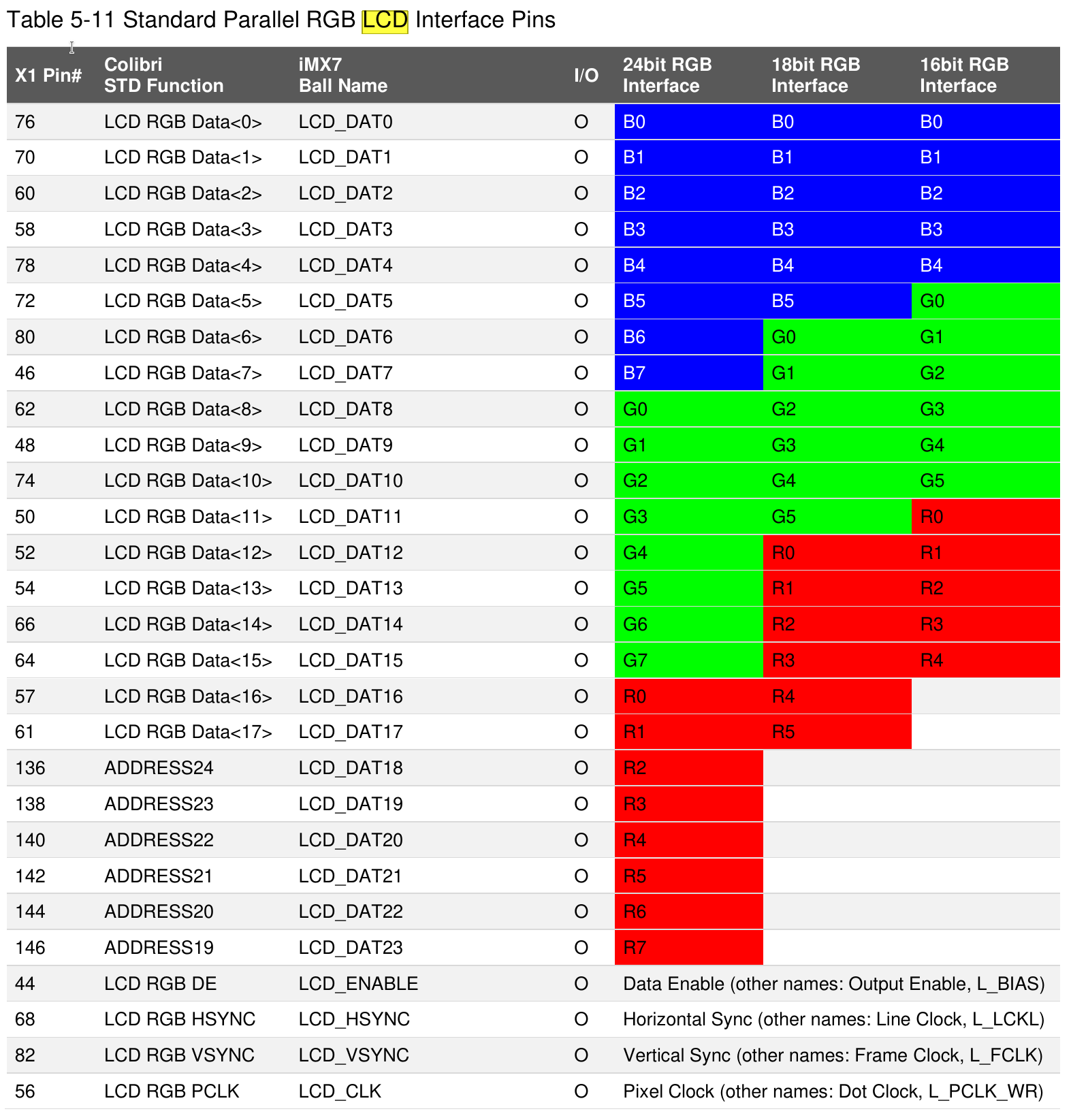
Based on the available documentation, I need to clarify that remapping individual LCD_DATA pins via pinctrl is not the correct approach for solving color channel swapping on the Colibri iMX7D.
Understanding the Architecture
The parallel RGB interface on iMX7D uses dedicated LCD data pins (LCD_DATA00 through LCD_DATA23) that are already configured for their LCD function. These pins carry the RGB data in a specific bit order that’s determined by the display controller (LCDIF), not by individual pin remapping(1).
Why Pinctrl Remapping Won’t Work
The MX7D_PAD_LCD_DATA## pins are dedicated display interface pins. They don’t have alternate GPIO or other functions that would allow you to “swap” them. The pinctrl subsystem controls pin function selection (muxing), pull-ups/downs, and drive strength—not the logical mapping of color channels(1).
Actual Solutions for Color Channel Swapping
Since the data-mapping property and offset settings aren’t working, and pinctrl remapping isn’t applicable, you have these options:
Option 1: Hardware Fix (Recommended)
If your custom carrier board has R and B channels physically swapped compared to the standard pinout, the proper solution is to correct the hardware wiring to match the standard Colibri iMX7D parallel RGB pinout.
Option 2: Software Workaround at Application Level
Since the kernel-level color format configuration isn’t providing the swap you need, you may need to handle this at the application/framebuffer level by implementing color conversion in your graphics stack or application code.
Option 3: Custom Kernel Driver Modification
You could potentially modify the LCDIF driver to swap the R and B channels, but this would require:
- Custom kernel modifications
- Maintaining those modifications across BSP updates
- This is not recommended for production
Verification Steps
Before proceeding further, please verify:
- Check if your overlay is actually being applied:
cat /proc/device-tree/chosen/overlays/your-overlay-name.dtbo
If it returns 0, the overlay was applied successfully(2).
- Examine the actual panel driver being used:
dmesg | grep -i panel
dmesg | grep -i lcdif
- Confirm your hardware wiring - verify which physical pins on your custom board connect to which LCD_DATA lines on the Colibri module.
Recommendation
Given that you have custom hardware with non-standard wiring, the most reliable solution is to correct the hardware design to match the standard Colibri iMX7D RGB interface pinout. Software workarounds for hardware wiring issues are fragile and difficult to maintain.
If hardware changes aren’t possible, please share:
- Your complete device tree overlay file
- The output of
dmesg | grep -E "panel|lcdif|display"
- Details about which specific LCD_DATA pins are swapped on your hardware
This will help determine if there’s any driver-level configuration we’re missing.
Best regards,
Toradex AI Assistant.
Did you like my answer? 

If I answered your question, please tick the “Solution” checkbox.
For follow-up questions to me, please use @ToradexAI in your post.