I am using the Verdin IMX8MM v1.1a in our own carrier board. We already use the CAN bus on the Verdin to talk to some pressure sensors and that appears to work fine. However, I have found a problem when trying to talk to a new device we would like to use. This only transmits and sends messages every 250 ms at 250 kbps.
After a fair amount of investigation I have got to:
The device I am talking to works ok when connected to a Korlan USB2CAN and Wireshark
When connected to my carrier with the CAN transceiver powered and enabled it works ok repeatedly sending a packet without getting and ACK
When I bring up the SocketCAN interface with ip link set can1 up type can bitrate 250000 the device sends a number of packets and these are received by my application but it gives up due to to many errors after about 30 attempts
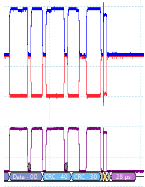
I think the reason is that the CAN controller on the Verdin board is not respecting the CRC delimiter length so the communicating device does not realise it has had an ACK so repeats the packet and then we start getting errors and then it gives up.
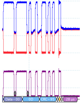
This is a good plot showing the ACK and a full width CRC delimiter:
Before diving so deep, did you check bitrates are OK? My favorite way to check it - jest let single node send something. Nothing else should be connected to the bus, just sending node and scope. Find minimum pulse width T. 1/T should match your bitrate. Any visible deviance from target bitrate is bad sign. You should check it for both, your Verdin and sensor.
You didn’t say you checked bitrate with scope. ip link bitrate is of course fine, but sometimes you need to check it physically. It could be driver bug, it could be something wrong with clock.
You may need as well to check sampling point position specified in your sensor datasheet and and specify detail timings using ip link set command, tq, prop-seg, phase-seg1, phase-seg2, sjw. MCP2517FD, difficulties with baud rate settings (force.com)
Different SPs lead to different lengths of the BRS bits and CRC delimiter bits in the different nodes.
^^ sounds having something to do with you first message.
Well, with such timing differences at least some messages should be received and acked. Sampling point usually affects long buses, it shouldn’t matter a lot at short distances.
Perhaps it has something to do with CAN FD capability of MCP2517FD? Could you try adding fd off at the end of your ip link set command? To see whole list of other ip link settings use ip link set can0 type can help.
Regarding issuing ip link set from python vs no python. Are you sure interface name is the same in both cases?
Hi @Edward
I haven’t made much progress the rest of today, thanks for your suggestions, I tried all the options I could find under the help section and no improvement. I am now in the position that:
Kimax2 transmits to the USB2CAN device correctly
Verdin transmits and receives to the USB2CAN device correctly
Kimax2 and Verdin together cause the CRC delimiter error and stop working after a short while
These are all connected in all states just with different devices enabled on the bus. Electrical signals look good, low noise and ringing etc. Cable lengths are a few metres.
Can you think of anything I could measure about the working signals to identify the problem?
Or anything I could ask the supplier of the Kimax2 that might help understand the problem?
MCP2518FD I tried seems working well with zoo of MCUs from various vendors. I doubt MCP2517FD is much worse than that. But something is causing this problem for you. Is it transceiver, circuit issue, something wrong in MCP2517FD, something wrong with Kimax2? I don’t know. Do you know what MCU is used in Kimax2?
More information from the supplier: We are using the built in CAN controller of our PSoC5 microcontroller (Cypress semiconductors). The CAN controller implements the CAN2.0A and CAN2.0B specifications as defined in the Bosch specification and conforms to the ISO-11898-1 standard at a bit rate of 250 kbps.
I think I have resolved the issue, using the information from the supplier I set the sample point to exactly 0.813 and it worked. I had previously tried values around this area like 0.8 and 0.85 so that makes me a bit concerned that it needs to be so exact and, as far as I can tell, non-standard.
Thanks for feedback. Is it clear for you which node to blame or are you going to conduct more tests to determine which end is broken?
I haven’t met such situation yet, no idea how so strict SP could matter. Dominant bits shorter/wider than recessive? Too long edges in waveform? I don’t know