adrian
October 31, 2023, 4:24pm
1
I am using BSP6 and in the device tree i can change the operating frequency of the LCD output using
panel_dpi: panel-dpi {
compatible = "panel-dpi";
label = "lcddisp";
backlight = <&backlight>;
power-supply = <®_3v3>;
status = "disabled";
port {
lcd_panel_in: endpoint {
remote-endpoint = <&lcdif_out>;
};
};
panel-timing {
clock-frequency = <33300000>;
hactive = <800>;
vactive = <480>;
hfront-porch = <210>;
hback-porch = <4>;
hsync-len = <46>;
vback-porch = <2>;
vfront-porch = <22>;
vsync-len = <23>;
hsync-active = <0>;
vsync-active = <0>;
de-active = <1>;
pixelclk-active = <1>;
};
};
And the size is correct i.e. 800x480 but i believe the colors are wrong.
fbset gives
mode “800x480-0”
I believe i need bgra instead of rgba.
Up to now i have been building to BSP3 and i believe i changed a .c file to correct this (but this was a few years ago so i cannot remember)
With a module built to BSP3 i get
fbset
Just wondering why this shows timing values and the BSP6 does not ?
Hello @adrian ,
Could you please share a picture of this wrong behavior VS the expected behavior?
Best regards,
adrian
November 2, 2023, 3:19pm
3
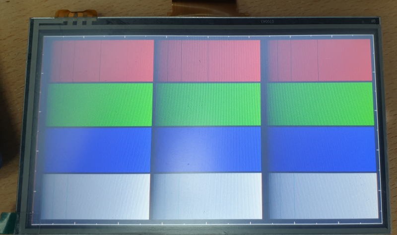
This is the same hardware with a IMX6ULL module built to BSP3
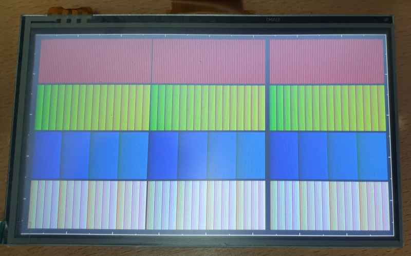
This is the same hardware with a IMX6ULL module built to BSP6
So the hardware must be correct , but the driver/settings needs changing
So it has been a while since i have had to rebuild the kernel and device tree for any hardware.
Hello @adrian ,
and yes, they mention mxsfb, and lcdif.lcdif instead of panel-dpi. In lcdif you can set the bits-per-pixel parameter, which I think it is the cause of your color artifacts.
Best regards,
adrian
November 3, 2023, 9:55am
5
Hello, i have taken a look at that link and i have tried adding ’ display-timings` into &lcdif but this does not work.
I am wondering if that page is out of date as with the build i am using there are no mention of ‘display-timings’ or ‘port’ or ‘compatible’
So from the build i have , i have the following
lcdif: lcdif@21c8000 {
Then …
panel_dpi: panel-dpi {
compatible = "panel-dpi";
backlight = <&backlight>;
power-supply = <®_3v3>;
status = "disabled";
port {
lcd_panel_in: endpoint {
remote-endpoint = <&lcdif_out>;
};
};
panel-timing {
clock-frequency = <33300000>;
hactive = <800>;
vactive = <480>;
hfront-porch = <210>;
hback-porch = <4>;
hsync-len = <46>;
vback-porch = <2>;
vfront-porch = <22>;
vsync-len = <23>;
hsync-active = <0>;
vsync-active = <0>;
de-active = <1>;
pixelclk-active = <1>;
};
};
&lcdif {
port {
	lcdif_out: endpoint {
		remote-endpoint = <&lcd_panel_in>;
	};
};
};
I am lost here as its very rare that i have to build a device tree for new hardware.
I have noticed this in the boot up terminal output
[ 1.739107] mxsfb 21c8000.lcdif: [drm] fb0: mxsfb-drmdrmfb frame buffer device
Q. Do i need to change a settings in my image config ( set via menuconfig) ?
Hello @adrian ,
I would suggest to read the documentation about device tree overlays (which is a feature available from BSP 5 on)
and then have a look at the integration of our Resistive Touch Display 7" Parallel screen as starting point for your display:
This is the overlay
which makes use of this device tree overlays:
And this other one to set the panel timings for the display
Best regards,