I am using WEC2013 and attempting to use the 40-pin extension connector on the Aster with my iMX7D module. Most of the pins function fine configured as GPIO, but I am having problems with those assigned to the CIF functions. The pins do not seem to function even though the API indicates they accept the GPIO configuration via the Toradex library. When I check with a logic analyzer, the pins simply do not respond to API calls to change level.
What is the trick to get the GPIO pins labeled with CIF* functions on the 40-pin extension to work as GPIO?
Thanks
Basically I want the CIF interface function OFF and all the CIF* pins available as GPIO. The datasheet is unclear how the hardware and software is to be configured to disable the CIF.
Dear @mmccullo
First Steps
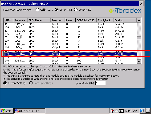
As a first step I recommend to use our iMX7 Gpio Tool to toggle some of the X40 pins:
Let’s make an example. In the Aster Carrier Board V1.1 Datasheet, Section 3.9.3 we find the following mapping:
- Aster.X40-16 = CIF_D_1 = SODIMM-98
Now we can use the GpioTool to modify the settings for this particular SODIMM pin 98:
The GpioTool also shows us the mapping to the i.MX7 specific GPIO number
This might not be relevant, but I mention it because many of our customers mix up the Gpio number with the SODIMM number.
Try to modify Direction and Level and measure how the state of the connector pin X40-16 changes. Make sure the AltFn is set to “GPIO”.
By Code
Now as you were able to change the pin state with the tool, you just need to do the same configurations in the code through the Toradex Ce Libraries.
Use the Gpio Demo application as a starting point. The basic instructions you need to execute are:
{
    HANDLE hGpio;
    uIo    x40_16   = COLIBRI_PIN(98);      // or   uIo x40_16 = GPIO(139);

    hGpio = Gpio_Init(NULL);
    Gpio_Open(hGpio);

    // Set X40-16 to "1" (Variant 1)
    Gpio_ConfigureAsGpio(hGpio, x40_16);
    Gpio_SetDir         (hGpio, x40_16, ioOutput);
    Gpio_SetLevel       (hGpio, x40_16, ioHigh);

    // Set X40-16 to "1" (Variant 2)
    Gpio_SetConfigString(hGpio, x40_16, NULL, L"altfn=-1,dir=out,lvl=1", StoreVolatile);

    Gpio_Close(hGpio);
    Gpio_Deinit(hGpio);
}
Regards,
Andy
Yes, thanks for that tutorial on the GPIB configuration, but I am already doing that. I got the gpib_demo app and proceeded to test every GPIO pin for output.
I found that on the 40-pin extension of the Aster all I/O pins work as output except:
- pin 15 (BL_ON, SODIMM 71) will cause a connected VGA display to blink OFF and ON
- pin 26 (CIF_D_8, SODIMM 86) will not change state from low
I am using the GPIO to emulate an 8-bit ISA (PC/104) bus and I had DATA4 connected to pin 26. It was not functioning. So I proceeded to move the line to pin 12 (GPIO18, SODIMM 59). This is not working correctly either as the line glitches – the ISA bus requires a bi-directional DATA bus and apparently that pin does not like switching direction (likely because of its pairing with IO(8), see below).
I had problems with the gpib_demo freezing when checking pins as inputs. ?? Have not followed up on this yet.
I have the GPIO library source code and found that SODIMM 59 is IO(117) which has some special code related to IO(8) as those pins are connected. I think your library code doesn’t account for switching direction for these pins (via GPIO_SetDir) and also changing its partner’s direction after the initial config.
I’ll probably opt to move DATA4 to another pin, and not use SODIMM 59 for bi-directional application.
I hope these “gotcha’s” help someone else trying to use the extension connector I/O.
Dear @mmccullo
Thank you for the detailed report. I have a few comments:
- X40-15 (BL_ON, SODIMM 71)
The default purpose of this signal is to turn off the backlight of an LCD, we use it also to turn off the VGA converter (IC10) on the Aster.
The VGA converter can be put into an always-on state by changing a resistor on the Aster board.
- X40-26 (CIF_D_8, SODIMM 86)
I’m surprised about this. I am able to switch between high and low without issues, using the GpioConfig tool.
The only circuit between the connector and the CPU itself is a 22Ω series resistor.
- X40-12 (GPIO18, SODIMM 59)
You found correctly, that there are 2 CPU pins shorted together. To use this pin as a GPIO, I recommend to do the following in your code:
- configure
GPIO(117) as GPIO, Input, using the GpioLib. This will make put the CPU pin ECSPI2_MOSI in high-impedance state, so it has no effect on the signal.
- use
GPIO(8) to change direction and pin level of SODIMM 59.
Regards, Andy