We have designed and manufactured a custom carrier board for apalis imx8 with reference to Ixora carrier board v1.2A. With reference to the original schematic.
We observe that,
3.3V, 5V_SW, 3.3V_SW are showing expected voltage levels on turning on.
POWER_ENABLE_MOCI = 3.3V
RESET_MICO# = 3.3V
But RESET_MOCI# is low and WAKE1_MICO# is at 1V( Not as expected)
In addition the Toradex seems not to start on Power on Reset and Soft Reset(with push button).
Do you think of any scenarios where such an observation could happen.
While I start to work on this problem can you supply a bit more information.
How are you building your OS and what OS version?
Are you able to do your testing with the Toradex supplied carrier board to see if you obtain the same results as your custom board?
And of these results, can you give a bit more detail how the are deviating from the chart on page 81 ,Figure 71 - Power Up Sequence. for the Apalis Carrier board design.
Can you give a bit more detail here? Is this on the Ixora carrier board v1.2A?
“How are you building your OS and what OS version?”
Ans- We are building the OS from Source provided by Qt(QT for device creation). The version is as follows
QT 6.2.6 , Yocto version 4.0.3
“Are you able to do your testing with the Toradex supplied carrier board to see if you obtain the same results as your custom board?”
Ans - We have tested with Toradex Carrier board and it works fine, The problem seems to be only in Custom Carrier board created by us.
" And of these results, can you give a bit more detail how the are deviating from the chart on page 81 ,Figure 71 - Power Up Sequence . for the Apalis Carrier board design."
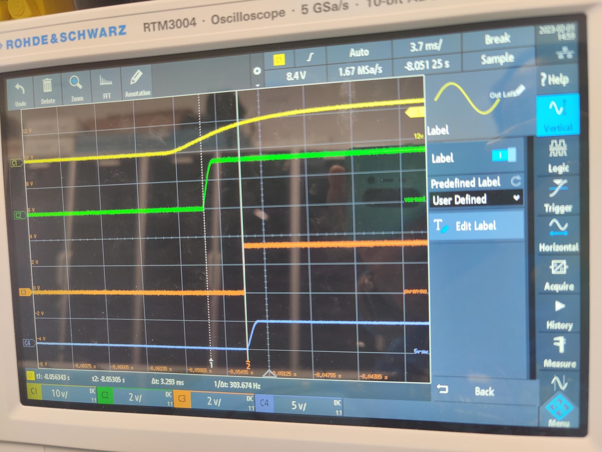
Our plan is to follow same power up sequence since we do not plan to change it from Ixora carrier board. In addition we have attached the outputs from Oscilloscope and a diagram to show what is really observed
Sorry Eric, to trouble you. But the issue was related to state of Recovery pin, We fixed it and It is booting now. We can consider this issue closed as of now. Thanks very much for your support and time.
please keep in mind that we have an errata on the WAKE1_MICO#
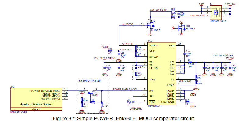
Moreover, there is an issue with the POWER_ENABLE_MOCI in some cases. This will be fixed in the new IXORA1.3 but you can already find some information in the Apalis carrier design guide.
on page 87.
Depending on the Apalis module, the POWER_ENABLE_MOCI signal is created from the module IO
voltage rail. If the backfeeding to the module interface pins is too high, it could cause an issue that
the POWER_ENABLE_MOCI signal does not go low enough for turning off the regulators (for
example, the AOZ2260QI-11). This means the power rails do not turn off in the module power-off
state. To prevent such issues, it is recommended to add a comparator circuit between the
POWER_ENABLE_MOCI output of the module and the regulators. The comparator should be set to
a threshold level of around 2.5V. Figure 82 shows a simple comparator circuit. R1 and R2 are used
for setting the threshold value