Hello,
I am trying to make a serial communication on the iMX6 with the GPIO and PWM pins available.
I use the GPIOs for sending commands and reading information and the PWM for sending a clock signal to the device that I need to read information from.
The problem is that I need to read information on every positive clock signal but the PWM 1 pin is just configured like in the given example.
Is there a way to read the current state the PWM signal or do I need to reconfigure the pin as a GPIO to do that?
Looks like you are trying to implement something similar to I2C. Could you please tell us more about the problem you are trying to solve?
It is similar to an I2C but uses more pins for communication and states.
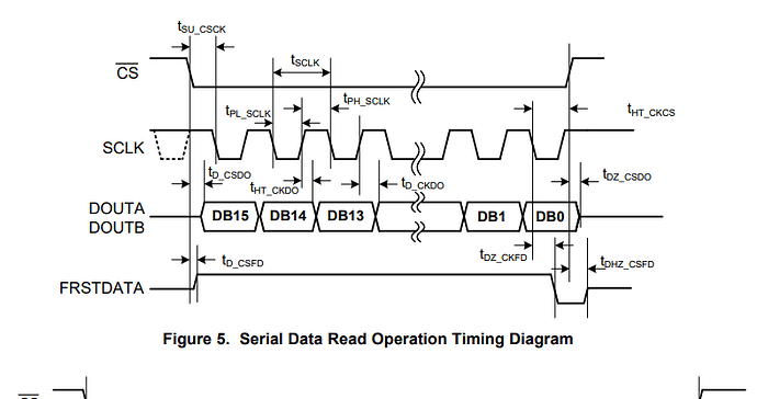
I have a CS pin which is GPIO3 as output, a FIRSTDATA pin which is an input from the device and is used for indication what is being sent on GPIO 5, BUSY pin again input on GPIO6, INA and INB which are data inputs on pins GPIO7 and GPIO8. And an output CLK signal where PWM1 is used for that.
For INA and INB I need to read a bit from each input on a CLK high signal.
So I want to be able to read the state of the clock in my C++ code so I can know when my CLK(PWM1) signal sends a high impulse to the device that I am reading, that means that the device is sending me a new bit and I can read it.
Changing the pins currently is not an option so I must use the one given to me.
What you see on the picture is called SPI. If you failed to connect your device to SPI pins, just use both clock and data as GPIO and toggle them appropriately.
As Edward state it’s definitely a flavor of SPI with some additions like FIRSTDATA signal. I’d recommend to use an embedded SPI controller to read data, plus check the state of FIRSTDATA signal using GPIO. Or you can use 4 GPIO lines and toggle clock line “manually” ie do a bitbang. Though using PWM for clock line theoretically is possible it’s much simpler to use the 2 methods described above.
Thank you for the information, I think I will go with bitbang as I cannot change the pins that are given and there are two input data signals.
