Apalis CAN Reference Schematic

G’day,

I’m reviewing the Apalis Carrier Board Design Guide, as well as the schematics for the Apalis Evaluation Board, with the aim of designing the CAN interface for my device. See below CAN schematic (Figure 49 from Apalis Carrier Board Design Guide) as a reference for my following questions.

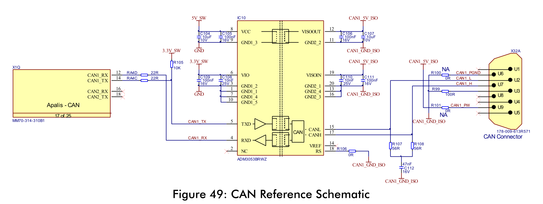
  1. Can I add the 120 Ohm termination resistor between CANx_L and CANx_H directly on the PCB? Referencing the figure above, the resistor would be between the traces connecting to U2 and U7 on the CAN Connector (CAN1_L and CAN1_H respectively).
  2. Is the isolated 5V supply (CANx_5V_ISO) purely a means for protecting the logic/Apalis side of the CAN interface? I will be interfacing with both externally powered CAN nodes (e.g. vehicle ECU) and non-powered external CAN nodes (e.g. sensor units) which required 12V+. As such, my CAN connector will not have the CANx_5V_ISO output as shown in the above schematic, and will be 4-pin only (12V+, GND, CAN_L, CAN_H), with the 12V+ and GND pins being optional. Is this acceptable?
  3. How should CANx_GND_ISO be connected to the system/PCB GND? The ADM3053BRWZ datasheet suggests they should be connected via a ferrite bead, but this isn’t shown in the schematic.

Thanks!

  1. High speed CAN bus should have 120 Ohm termination resistors on both ends. On Apalis side R107 and R108 acts as a terminator. So you don’t need an additional resistor on that side.
    [upload|h43b3z/1mjKwtsFAj/HfgjZdcps=]
  2. According to ADM3053 datasheet - “Isolated Power Supply Input. This pin must be connected externally to VISOOUT. It is recommended this pin have a 0.1 μF capacitor to GND2 (Pin13 or Pin 11). Connect this pin through a ferrite bead and short trace length to VISOIN for operation.” So you have to connect that 2 pins together even if you are not going to use 5V insulated supply.
  3. CANx_GND_ISO should not be connected to system/PCB GND. All CAN bus signals must be galvanically insulated from Apalis module. Datasheet recommends to connect Pin 11 and Pin 13 together through
    one ferrite bead to the PCB ground. But it’s a CAN side ground which is not connected to Apalis ground.
    [upload|H7DWJGi2etoXhgPVZD/494bdUv4=]

Thanks @alex.tx, that all makes perfect sense. I had wondered whether R107 and R108 were the terminating resistors, thanks for clarifying. I’ve connected VISOOUT and VISOIN (with the required capacitors to GND2) as per your second point. I misunderstood the ‘system/PCB’ ground in the ADM3053 documentation, but I understand it now. Thanks!

Hi @jars121,

Please note that the termination resistors on the CAN interface are generally part of the cable and ideally, should only be used at the 2 ends of the CAN bus (as shown in the image: can-iso11898-2-network.png (alex.tx comments above).

For the PCB layout reference, please refer to the Ixora carrier board CAE data, which uses ADM3053 (CAN Transceiver).

Reagrds,
Satyan

Thanks @satyan.tx. I don’t have Altium unfortunately, otherwise I would definitely have poured over those documents. Point taken regarding the use of the terminating resistors; your comment aligns with my understanding.

Hi @jars121,

In case you want to refer to the design files, you can use Altium Designer Viewer available for free.

Regards,
Satyan

Thanks @satyan.tx, I actually wasn’t aware of that application, that should be a huge help!