Hi, it is my first post so please have mercy I searched the forums, but did not find an answer for my question. I am also a beginner in SoC programing.
I am working with shift registers (74HCT595 for sending data and 74HC165N for reading data) and the spi bus on port 1. I am using the SPI library (in C). My problem is the cs0.
It is wired as CS of the 74HCT595. Sending Data works fine.
For reading data (74HC165N) I am using an custom gpio as PL (parallel load, no cs needed). I works too but during the read process the cs0 is set to low (of course) and the output data on 74HCT595 gets messed up. How can I prevent this (for reading only) while my programm is running. Can I reconfigure or disable the CS0?
Please quickly check if the there is no spi CS set for the SPI channel you are using, if the pin is tristated, this is fine. The function call above will not remove any setting that was set previously.
Im getting errors when I try to set this:
ERROR: GPIOLib: Invalid GPIO
Unknown: DEBUGCHK failed in file .\src\gpio_teg.c at line 231
SDS-CH-Tests.exe hat einen Haltepunkt ausgelöst.
Spi Error: Illegal Gpio value
Unknown: DEBUGCHK failed in file .\src\spi_teg.c at line 585
SDS-CH-Tests.exe hat einen Haltepunkt ausgelöst. (means Interrupt happened)
The first DEBUGCHK is not nice but actually fine. The SPI lib tries to set a “None” pin in the using the GPIO lib which triggers an assert, actually this function does nothing at all. So if you want to get rid of the ASSERT, just remove the Spi_SetConfigInt for the ioCS at all. Just make sure, there is no CS set for that SPI channel or use one that is not attached to any device.
Hi @samuel.tx, I know this is an older thread but I just ran into exactly this problem. I am realizing that we probably made a bad choice when assigning CS pins in our design, but the hardware has been delivered and now I need to make it work. We are using the T20 with Win CE7 and Toradex library 2.1. We are using only one SPI channel (Channel 1) in order to use the standard Colibri pin-out to keep the pathway open to migrate from the T20 to the iMX6 or IMX7. We are using multiple SPI devices with one CS line per device. One of those devices uses pin 86 as its CS, which is the default for CS0 for SPI1. The other CS lines are just normal GPIO pins. We want to just select a CS line by setting a GPIO pin then read and write over the SPI bus. Unfortunately, the SPI library always asserts pin 86, which then causes a conflict with the other CS which we asserted using GPIO.
I can’t configure the SPI port to use either of the other legal pins (34 or 113) because we have used those for a different purpose in our design.
One of our SPI devices also requires a different SPI mode, so to talk to that device I need to close the SPI device, switch the mode, then re-open it. Every time I do that the SPI driver reasserts control of pin 86.
I’d like to set the CS pin used by the driver to -1 or ioNone but if I do that then I get a debug assert as described above, and I get it every time I reopen the port to switch the mode which is unworkable. The SPI driver boots up with the CS pin set to 86 by default.
I have found a work around which is to configure pin 86 as a GPIO after I open the SPI port, and I need to do that every time I reopen the SPI port to switch its mode. This workaround does work but it seems clumsy. Is there a more elegant solution?
Hi @sahil.tx, yes, that’s exactly right. Only one of the SPI devices uses pin 86 as a chip select so I need to prevent the library from using it each time I send data on the bus.
Every time you open Spi port, it applies the configuration set by you. So, if the library finds that the configuration is not proper, it is bound to give you warnings/errors.
In your case, if you do not set any ioCS pin then it will take the default configuration which we have configured in the library and will assert pin 86, but if you set the configuration in the program, it will override the default values.
Setting ioCS pin to ioNone should actually throw error and that is why you are getting that error but this error is
actually fine as it does not stop your application.
You can also set the Spi pin to ioNone in the registry if you do not want to set it in your application.
eg add this in your application once
Spi_SetConfigInt(hSPI, L"ioCS", ioNone, StoreToRegistry);
or manually set it in the registry editor (HKEY_LOCAL_MACHINE\SOFTWARE\Toradex\SPI1)
ioCS REG_DWORD 0xffffffff
Your application will take these configurations from the registry every time you open the SPI port.
An interesting update on this old topic as we’re migrating from the T20 to the iMX6. The workaround I described above still works for the T20: set the chip select pin as a GPIO after opening the driver. But that workaround does not work on the iMX6. With the iMX6 it is necessary to use the code suggested by Sahil:
I’m an engineer working under Michael Snadden at Coherent Corp and I’m working on a variant system similar to what Mike was working on in this TS thread " 2 Devices on 1 SPI Port, CS0 problem"
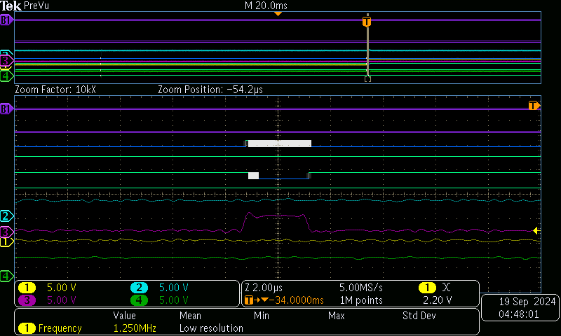
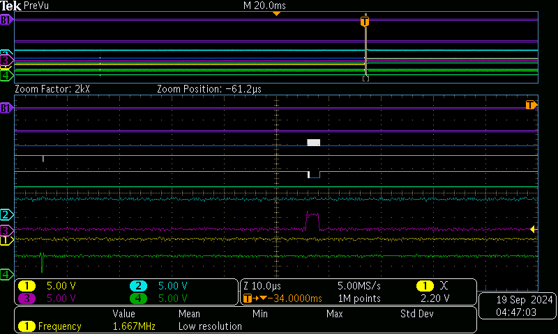
The system that I’m working on now is very similar to the one in the above thread. The main difference is in this system, only 1 SPI port is being used to talk to multiple devices using GPIO ports for each device CS. An FPGA is using the standard pin 86 as it’s CS, an ADC is using pin 70 as it’s CS. For the most part communication is fine when addressing the FPGA and ADC using this port 1, but what I’m seeing is on average over the span of 8-10 hours of the system happily running without issues, the SPI port will have a random spurious CS access (pin 86 going low) for a very short time time, < 1us, and this will initiate a read cycle with clock cycles on the bus, with the CS line in the high state! The data will be read as 0xFFFF, which our code will be read as a fault condition. I have captured scope images showing this weird CS “blip” and the resulting clock cycles for some bus access. I’ve used a TPx location on our h/w board to signal when this faulty read occurs and captured the previous read on the bus that initiated the fault bit. The scope trace shows this “blip” in the CS (pin 86) and the subsequent clock cycles. I even temporarily removed all other devices from using this SPI port (ADC code removed for testing to make sure it wasn’t interfering with the SPI comm).
What in your opinion is causing this seemingly random CS “blip” on the default pin 86?
In those trace pictures, the blue probe trace is MISO, cyan probe trace is SCLK, yellow probe trace is TP6 (GPIO activated in f/w), the lower green probe trace is the CS (pin 86);
the digital signals are the sclk, CS, MISO, MOSI above. You can see in tek00003.png the CS “blip” and tek00004.png shows the zoomed in clock cycles during the phantom “read” operation when CS is in the high state.
Any ideas on this? This system is using the imx6 Colibri module, replacing the T20 due to its end of life timing. We are also debugging a similar ADC read issue that will also return spurious 0xFFFF reads on occasion too and that currently is on the same platform that Mike originally sent those TS questions previously.