Hi @vishalborle92 ,
Based on the schematics and the Device Tree, I have a few more observations/questions:
-
The Verdin iMX8MP provides two USB interfaces capable of SuperSpeed operation.
-
In the default BSP:
-
From the schematics, it appears that you have implemented USB 3.x on USB_1. This differs from the Verdin standard, which explains why the Device Tree needs to be adapted for your hardware.
See Section 5.5 of the Verdin iMX8MP Datasheet and sec 2.4 of Verdin carrier board design guide
I have a couple of questions:
-
Was there a specific reason for implementing USB 3.x on USB_1 instead of using USB_2, which is already configured as the default USB 3.x Host interface in the BSP?
-
Since USB_1 is the default OTG interface and is also used for workflows such as USB recovery and remote display, have you considered how these workflows would be handled with USB_1 configured as a permanent Host on your custom carrier?
Regarding production programming, one possible approach would be:
-
Use a Toradex reference carrier board for the initial programming. This would avoid the need to maintain a customized TEZI image, and once the module is programmed with your custom image, it can be used on your custom carrier board.
-
If programming is performed directly on your custom carrier board, then a customized TEZI image matching your hardware would be required as part of the programming process.
Hello @sahil.tx
Great information..!!
There is no any specific reason to use USB_1 instead of using USB_2, We made recovery option provision on hardware but currently we don’t want to use that. Because by using USB C Type pen drive we are able to upgrade the SoM.
Since we are planning another hardware revision, we are considering swapping all USB_1 signals to USB_2. If we make this change, will we still need to modify the default Tezi device tree, or will stock Toradex Tezi work out-of-the-box for initial programming?
Regarding your suggestion to use a Toradex reference board (like the Ivy carrier board) for initial programming to avoid maintaining a custom Tezi image: while that works technically, it isn’t feasible for our factory production line. We need a solution that works directly on our custom hardware.
Just need to clarify if we used USB_2 verdin internal port then without modify the TEZI should work for flashing SoM using USB C Type stick with both orientation A/B is this correct?
Thanks,
Hi @vishalborle92 ,
I am looking into what changes would be required if the USB Type-A connector is replaced with a USB Type-C connector on USB_2.
Meanwhile, I have a few questions to better understand your production requirements:
-
Does your carrier board include an SD card slot? If so, would SD card-based programming be an acceptable option?
-
Does your carrier board have Ethernet connectivity? If yes, would network (Image Server) based programming be an option?
-
Is there a specific application requirement for using a USB Type-C connector?
-
If the port is intended only for flashing from a USB flash drive, would using a USB Type-A connector together with a USB-A to USB-C adapter be an acceptable solution?
Hello @sahil.tx
To answer your questions:
- SD Card slot is available but in factory they accepted only USB option, as SD card very tiny it difficult to handling during production.
- Yes Ethernet connectivity available, but by using this option I think laptop is required to connect with our carrier board for programming. Is this option how support first time programming? This option may not feasible for us.
- Our product hardware is intended to support our customer at least next 15 years in market. we used latest type of connection that mostly used now a days Type-C connector.
- This C Type port is not just used for flashing the SoM but it also used for data logging from application. We used C Type because currently most of systems is using Type-C instead A type.
I hope you get now understood on your questions.
Please let us know regarding the USB Type-C connector on USB_2 we are waiting for your confirmation yo update our schematic. Also please discuss internally with software team once we did this change will work USB C-Type both side A/B without modifying the Tezi?
Thanks.
Hi @vishalborle92 ,
Taking reference from the Verdin Carrier Board Design Guide:
“Since the USB-C connector is rotationally symmetrical, the USB-C receptacle needs to be able to provide the SuperSpeed signals on both sides. The connector orientation is detected using the CC signals. This information is required for controlling an analog multiplexer. The multiplexer switches the SuperSpeed signals between the TX1-RX1 and RX2-TX2 positions.”
Based on the above, if the USB Type-C DFP implementation handles cable orientation detection and SuperSpeed lane switching autonomously in hardware (using a CC controller and SuperSpeed multiplexer), we would not expect additional USB Type-C-specific device tree changes.
The changes you currently made are mainly required because USB_1 was repurposed for USB 3.0:
-
USB_1 was changed from a USB 2.0 (High-Speed) port to USB 3.0 (SuperSpeed). Since USB_2 already supports SuperSpeed, we would not expect this change to be required.
-
USB_1 was changed from a Dual-Role (DRP/OTG) port to a dedicated Host port. Since USB_2 is already configured as a Host port, we would not expect this modification to be necessary.
-
Similarly, the removal of the USB role-switch would not be expected when using USB_2.
One point to note is that, in our Verdin carrier board reference designs, USB_2 is connected to an on-board USB hub. If your custom carrier board instead connects the USB Type-C receptacle directly to USB_2 (without a USB hub), the corresponding USB hub node in the device tree would no longer describe the actual hardware and should be reviewed. However, we would not expect the absence of the USB hub itself to prevent a USB mass storage device connected directly to the USB Type-C port from being detected and enumerated by the USB host controller.
Overall, assuming the USB Type-C implementation on USB_2 follows the reference architecture and the CC controller/SuperSpeed mux operate autonomously in hardware, we would not expect the USB controller-related device tree changes that were required for your current USB_1 implementation.
Hello @sahil.tx ,
Thanks for this information..
If we moved to decided to use USB_2 from USB_1 port to understand in more details need clarification on below.
In our existing schematic we did following configuration:
- The port pin of TUSB320L chip is pullup for used only DFP mode.
- ADDR pin is not connected because we are using GPIO mode, no I2C enabled in main Linux device tree.
- We need only Host mode (DFP) The application is only connect Type-C Pen drive.
When we use USB_2 then what is role of CC1 and CC2 pins of TUSB320L chip? In USB_2 driver how it work for GPIO mode?
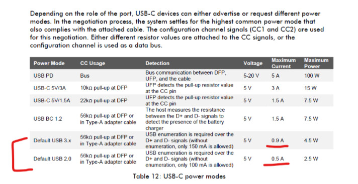
Is the OUT1 and OUT2 pin of TUSB320L is reading internally in driver what is default maximum current configuration as per below table?
Thanks,
Hi @vishalborle92 ,
To settle your queries regarding the hardware implementation of USB Type-C with USB 3.x, I would suggest referring to the Toradex OSM Development Board design as a reference.
It includes a USB Type-C interface with USB 2.0/3.x SuperSpeed support, along with the required Type-C control, VBUS, and SuperSpeed switching circuitry.
The USB switching and muxing architecture is also documented in Section 2.19.4 of the datasheet, which provides a good reference for the overall hardware implementation.
You can use this design as a reference while finalizing your USB Type-C implementation on the custom carrier board.
Thanks @sahil.tx we will check this.