Hi @Edward,
I couldn’t see the images in your post, I can’t follow that url either. Not sure what is going on.
Thanks for looking into this, please keep us updated.
Increasing the SPI clk has helped on my design but I can still generate the TEFIF error when I push the bus harder. We are trying some different combinations of the things you suggested today.
Would be good to have a contact at NXP to weigh in. @andrecurvello.tx is there anyone we can share this thread with?
Thanks, I reloaded pictures. I wonder who or what deleted them.
I’ve question for you. Did you check with scope the percental idle/busy times while pushing the bus harder. Perhaps you are close to real limits and driver just doesn’t tell you about it? Depending on scope used, something like RMS of /CS (with known CS high voltage) could tell % of busy time. Typical SCK/CS waveform taken while TEF error is about but not yet triggered could help as well. Real message rate numbers could help as well? I see you wrote above about messages per second per device. But then you didn’t mention how many devices you have, what is overall messages per second rate? With updated SCK clock of course.
Hi @Edward,
Thanks for your work on this. I don’t have easy access to the SPI bus as it is on the SOM only in my design. On the CAN bus I can see utilisation is pretty low, duty cycle around 1% when stable. At 14% I get a fault within a few seconds.
With the increase in SPI clock I can run the system at the rate I need so the priority of this problem has dropped for me. I did have another look this morning and it is possible I have a problem with my code, it looks like when configuring the second device something goes wrong, maybe the first one is responding and causing a conflict. This is eased with a slower update rate as I can configure both devices before the first reports.
In answer to your questions:
2 x HPT1400 pressure sensors from Hydac
Transfer is 2 values around 8 bytes
Works fine with both devices sending at 250 Hz but starts faulting at 333 Hz
Thanks for your response, I thought better to respond here than in the comment as there is more space. In terms of config I don’t think we have changed anything from standard. @gauravks has written our devicetree overlay which adds an additional MCP2518 to our carrier on SPI_1.
If you want to recover from error, you may try rmmod mcp25xxfd then modprobe mcp25xxfd driver, of course if it is compiled as module. It is not hard to fix down/up recovery, but I need to switch to other tasks for now.
I’m able to reproduce your TEFIF issue. It happens on my side when sum of Rx traffic + Tx traffic is about to reach CAN bus capacity at 1Mbps. This mcp25xxfd driver is able receive all 1Mbps bus traffic on iMX7D, well above than 9k messages per second and still is able to send receive messages. I have means to produce burst of ~5k msg/s from iMX7D. TEFIF appears when there’s another bus traffic of about 4k msg/s. Like you ifconfig down/up doesn’t recover from TEFIF error. rmmod/modprobe helps. You said you have much more modest traffic and that is weird.
@andrecurvello.tx, regarding mcp251xfd driver from main line. It is much less capable regarding Rx traffic. Crossing 6k msg/s level dmesg gets filled with RX FIFO overflow. But a good point I was not able to break it sending burst of messages. Though burst as well is much less capable than using mcp25xxfd driver, I’m unable to send the same burst at the same 5kmsg/s speed like using current driver. Regarding RX FIFO, perhaps it is partitioned in favor of TX FIFO or TEF FIFO length.
TEF (transmit event FIFO), which allows to register order on which TX messages appear on the bus + register timestamps of each TX, is optional thing. It looks great, but it takes device memory and thus reduces TX and RX FIFOs and TX queue. Current driver of course shouldn’t have any issues if TEF size (N of message events) matches sum of TX FIFOs and TX queue. I’ll look at it later. I hope it’s fixable.
Did you see latest MCP2518FD errata and datasheet. Last datasheet I saw had 20MHz SPI clock limit. Now it dropped to 17MHz. It’s weird my VF61 communicated flawlessly with MCP2518FD at 20.8MHz and iMX7D breaks with the same MCP2518FD click board at 20.0 MHz. There are other issues listed in errate. CRC, ECC, memory corruption… Issues with MAB were listed in previous errata, now it is missing in last edition. System error description in “MCP25XXFD Family Reference Manual” about MAB now just tells there is something like that without any details when it can happen. Older errata mentioned that the gap between 2nd and 3rd SPI byte had to be shorter then some amount of microseconds depending on CAN bit rates. Perhaps some issues are not yet registered, which could lead to problems at modest CAN bit and message rates like in your case? I hope it’s just driver issue.
First of all the thanks for this Investigation. Could you move back to use GPIO for the chip selects instead of Hardware chip selects and let us know if you still see an issue with the internal SPI Can Controller?
Thanks and best regards,
Jaski
As a supplementary question:
Even when I bring the CAN interface DOWN then UP again there seem to be some faults that it is not possible to clear. These are fixed by a reboot, is there a way to power cycle the CAN controller on the SOM without rebooting?
This is the pattern I am seeing while the device is working ok, I will have to try to replicate the fault and get the log for the locked up version. I am just relying on the Python library raising exceptions to me to tell something has gone wrong.
[ 3402.662050] IPv6: ADDRCONF(NETDEV_CHANGE): can1: link becomes ready
[ 3404.320570] mcp25xxfd spi2.0 can1: tefif: fifo 0 not pending - tef data: id: 00000000 flags: 00000000, ts: 00000000 - this may be a problem with spi signal quality- try reducing spi-clock speed if this can get reproduced
[ 3404.340697] mcp25xxfd spi2.0 can1: tefif: fifo 0 not pending - tef data: id: 00000000 flags: 00000000, ts: 00000000 - this may be a problem with spi signal quality- try reducing spi-clock speed if this can get reproduced
[ 3404.360404] mcp25xxfd spi2.0 can1: tefif: fifo 0 not pending - tef data: id: 00000000 flags: 00000000, ts: 00000000 - this may be a problem with spi signal quality- try reducing spi-clock speed if this can get reproduced
[ 3404.442912] mcp25xxfd spi2.0 can1: tefif: fifo 0 not pending - tef data: id: 00000000 flags: 00000000, ts: 00000000 - this may be a problem with spi signal quality- try reducing spi-clock speed if this can get reproduced
[ 3404.462628] mcp25xxfd spi2.0 can1: tefif: fifo 0 not pending - tef data: id: 00000000 flags: 00000000, ts: 00000000 - this may be a problem with spi signal quality- try reducing spi-clock speed if this can get reproduced
[ 3409.616525] audit: type=1006 audit(1616402779.554:63): pid=14544 uid=0 old-auid=4294967295 auid=1000 tty=(none) old-ses=4294967295 ses=21 res=1
[ 3421.022718] IPv6: ADDRCONF(NETDEV_CHANGE): can1: link becomes ready
[ 3421.249937] inv-mpu6050-i2c 2-0068: spurious interrupt with status 0x4
[ 3516.603615] audit: type=1006 audit(1616402886.543:64): pid=14963 uid=0 old-auid=4294967295 auid=1000 tty=(none) old-ses=4294967295 ses=22 res=1
[ 3527.915936] IPv6: ADDRCONF(NETDEV_CHANGE): can1: link becomes ready
[ 3528.123150] inv-mpu6050-i2c 2-0068: spurious interrupt with status 0x4
[ 3741.015239] audit: type=1006 audit(1616403110.950:65): pid=15709 uid=0 old-auid=4294967295 auid=1000 tty=(none) old-ses=4294967295 ses=23 res=1
[ 3751.574088] inv-mpu6050-i2c 2-0068: spurious interrupt with status 0x4
[ 3752.418067] IPv6: ADDRCONF(NETDEV_CHANGE): can1: link becomes ready
[ 6016.322939] IPv6: ADDRCONF(NETDEV_CHANGE): can1: link becomes ready
[ 6019.484732] mcp25xxfd spi2.0 can1: tefif: fifo 0 not pending - tef data: id: 00000000 flags: 00000000, ts: 00000000 - this may be a problem with spi signal quality- try reducing spi-clock speed if this can get reproduced
[ 6019.505212] mcp25xxfd spi2.0 can1: tefif: fifo 0 not pending - tef data: id: 00000000 flags: 00000000, ts: 00000000 - this may be a problem with spi signal quality- try reducing spi-clock speed if this can get reproduced
[ 6019.524978] mcp25xxfd spi2.0 can1: tefif: fifo 0 not pending - tef data: id: 00000000 flags: 00000000, ts: 00000000 - this may be a problem with spi signal quality- try reducing spi-clock speed if this can get reproduced
[ 6019.618120] mcp25xxfd spi2.0 can1: tefif: fifo 0 not pending - tef data: id: 00000000 flags: 00000000, ts: 00000000 - this may be a problem with spi signal quality- try reducing spi-clock speed if this can get reproduced
[ 6020.580758] IPv6: ADDRCONF(NETDEV_CHANGE): can1: link becomes ready
[ 6022.144449] mcp25xxfd spi2.0 can1: tefif: fifo 0 not pending - tef data: id: 00000000 flags: 00000000, ts: 00000000 - this may be a problem with spi signal quality- try reducing spi-clock speed if this can get reproduced
[ 6022.164611] mcp25xxfd spi2.0 can1: tefif: fifo 0 not pending - tef data: id: 00000000 flags: 00000000, ts: 00000000 - this may be a problem with spi signal quality- try reducing spi-clock speed if this can get reproduced
[ 6022.184364] mcp25xxfd spi2.0 can1: tefif: fifo 0 not pending - tef data: id: 00000000 flags: 00000000, ts: 00000000 - this may be a problem with spi signal quality- try reducing spi-clock speed if this can get reproduced
[ 6022.266913] mcp25xxfd spi2.0 can1: tefif: fifo 0 not pending - tef data: id: 00000000 flags: 00000000, ts: 00000000 - this may be a problem with spi signal quality- try reducing spi-clock speed if this can get reproduced
[ 6023.700186] IPv6: ADDRCONF(NETDEV_CHANGE): can1: link becomes ready
[ 6823.694062] audit: type=1006 audit(1616406193.582:66): pid=18792 uid=0 old-auid=4294967295 auid=1000 tty=(none) old-ses=4294967295 ses=24 res=1
[ 6834.196452] inv-mpu6050-i2c 2-0068: spurious interrupt with status 0x4
[ 6835.060582] IPv6: ADDRCONF(NETDEV_CHANGE): can1: link becomes ready
[84610.398108] audit: type=1006 audit(1616483979.149:67): pid=59749 uid=0 old-auid=4294967295 auid=1000 tty=(none) old-ses=4294967295 ses=25 res=1
Please use Wayback Machine to compare with previous versions. Wayback doesn’t offer PDF’s, but differently named files are still present on www.microchip.com.
Thanks for pointing this out, a contractor did our hardware design and I have not checked the sheet myself. On our carrier we currently use a 20 MHz SYSCLK which would limit the SPI rate to 8.5 MHz.
@jaski.tx or @matthias.tx can you confirm what crystal is used on the SOM? I guess 40 MHz?
Thanks, yes I see where you mean. This will affect the maximum clock rate. Is there a limit you recommend? Looks like SYSCLK/2 * 0.85 to me which is 8.5 MHz.
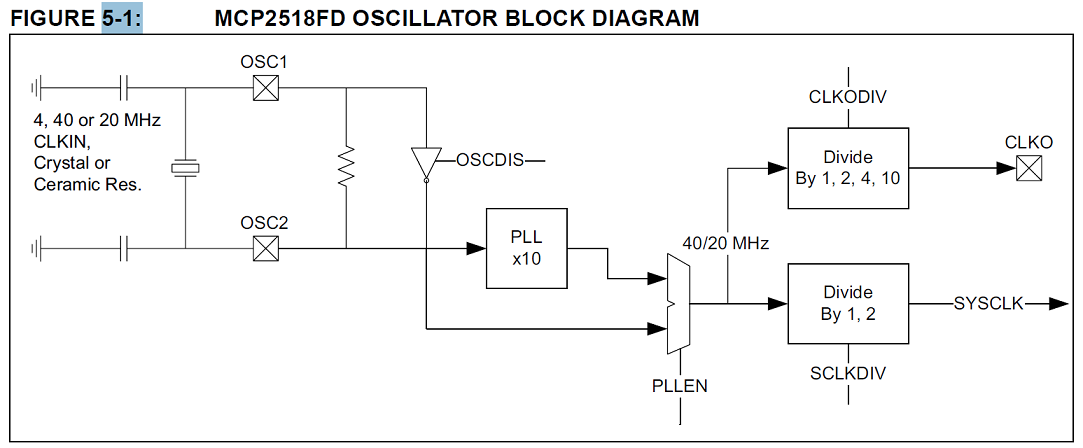
20MHz MCP251xFD clock is worst option. With 20MHz 8Mbps data rate is not possible, only 4Mbps. Someone may need that fastest option. MCP251xFD PLL is fixed on 10x multiplier, so either it should be 4MHz + PLL or 40MHz without PLL.
Regarding SPI clock, yes, it should be SYSCLK/2*0.85, or 8.5MHz in your case. Driver may further limit SPI clock specified in DT. mcp251xfd driver I saw checks SPI clock frequency, don’t about mcp25xxfd driver.
Thanks for this Information. We will check this internally.
Hi @edwaugh, could you provide a sample of the python code and information about your setup thus we can try to reproduce your issue?
20MHz MCP251xFD clock is worst option. With 20MHz 8Mbps data rate is not possible, only 4Mbps.
Did you test this on your side?
Someone may need that fastest option. MCP251xFD PLL is fixed on 10x multiplier, so either it should be 4MHz + PLL or 40MHz without PLL
This is not entirely true, if you have clock of 40MHz, this will be anyhow divided by 2 in resulting 20 MHz (Figure 5.1 of the Datasheet of MPC2518FD).
The issue is that the SPI clock is limited to 8.5 MHz. Does this fit your requirements or not?
Are we talking about the same figure? SYSCLK has options:divide by /1 or divide by /2. This matches what I see in Figure 5-1. As well it matches OSC.SCLKDIV bit description. SCLKDIV: System Clock Divisor. 1-SCLK is divided by 2, 0-SCLK is divided by 1.
20MHz SYSCLK is not enough for 8Mbps data rate. 20/8 had to be at least divisible, it isn’t.