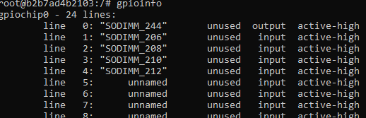
We still have a problem with MCU_GPIO pins. Is there some special configuration needed in device tree for them to work. We use on our carrier board SODIMM 141, 206, 208, 210, 212 and 244. All of witch are in MCU_GPIO0 and none of them work. When we write gpioset 0 0=1 and read back with gpioget 0 0 the value is still reported 0 and there is no change in voltage on the trace. However when we run gpioinfo it shows that SODIMM 244 changes into output after the gpioset command.
In short, you will disable the nodes that are currently using those pins with their alternate functionality and add device nodes to declare them as GPIO. The example on that page is for Apalis i.MX8 but should give you the idea.
My colleague pointed out to me that the gpioset utility only holds the value while the process is running. You can run it and add --mode=time --sec=5 to the command line to have it run and hold the value for 5 seconds. In another window, while that process is active, you should see the updated values using gpioget.
Those kernel configs should be enabled by default (as a module) if you are using our Torizon OS. It may be that the BSP reference images do not enable them by default.
We got the MCU_GPIO also working but in our board there is button on UART0_RTSn line and we thought that we can define UART0 only with RX and TX lines and RTS line is free to use as GPIO.
But when the fingerprint_uart2 is defined as shown below the device tree compiler gives error without any explanation.
So did we compose our device tree overlay with some mistakes or is it not allowed to use only part of devices pins? It compiles when we comment out the &fingerprint_uart2 block.
we figured out that we can’t use just any name like “&fingerprint_uart2”. As I understand there are device names that are predefined in files like k3-am62-main.dtsi.