hi @jaimeibk
Ok, feel free to share your findings.
Best regards,
Jaski
Hi, all
So I went back to check everything. Here’s some of things I found:
The connection from the cap_touch sensor and the board has six pins. VDD-GND, SDA-SCL, and two more: INT & SHUTDOWN.
INT is wired to pin 133 SODIMM in the Colibri-imx6
SHUTDOWN is wired to pin 127 of the SODIMM.
Pin 133 is mapped to pad NANDF_D3. (alt functions: NAND_DATA03, SD1_DATA7, and GPIO2_IO03)
Pin 127 is mapped to pad NANDF_D6. (alt functions: NAND_DATA06, SD2_DATA6, GPIO2_IO06)
Both are configured as GPIOs here (lines 466 and 467.
Up until this point, all good I think. But then I go to my overlay script:
/dts-v1/;
/plugin/;

/{
        compatible = "toradex";
        fragment@0 {
                target = <&i2c3>;
                __overlay__ {
                        clock-frequency = <100000>;
                        gsl1680: touchscreen@40{
                                compatible = "silead, gsl1680";
                                reg = <0x40>;
                                interrupt-parent = <&gpio2>;
                                interrupts = <3 2>;
                                power-gpios = <&gpio2 6 1>;
                                touchscreen-size-x = <800>;
                                touchscreen-size-y = <480>;
       /*                         touchscreen-inverted-x;
                                touchscreen-swapped-x-y;*/
                                silead,max-fingers = <5>;
                        };
                };

        };
};
So, my first assumption was that by declaring the interrupt-parent = <&gpio2> and interrupts = <3 2>, it would take GPIO02_IO03 as an input with IRQ_TYPE_EDGE_FALLING 2. Hence, the 3 and the 2 between brackets. I am guessing that is not the way because in the same link, both pins are under gpio…? I am a bit confused.
The other assumption was that by using power-gpios = <&gpio2 6 1>, I would be setting GPIO_IO06 as an output with a High.
I assume that this might be what is keeping it from working.
One last thing: after I modprobe the driver and do lsmod, I see the driver alright, but in the Used by column it shows a 0, which does not look right to me.
Can someone shed a light?
Thanks in advance!
Hi @jaimeibk,
Your syntax seems correct in how you reference the GPIO. I think the main issue is that the device tree you linked where SODIMM 133 and 127 are allocated as GPIOs, is not the device tree being used by Torizon.
You have the right file, but you’re looking at the wrong git branch, you’d want the 4.20 or 5.3 branch depending on which version of Torizon you’re working on. In those branches I don’t see SODIMM 133 and 127 allocated as GPIOs.
Man, I cannot believe I did not see that before!
So let me know if I got the flow correctly:
I need to have a first overlay where I allocate SODIMM 127 and 133 as GPIOs (I can just add it to the same overlay that deals with the 24bit line display, build, validate, and enable, as so:
/dts-v1/;
/plugin/;
#include "imx6dl-pinfunc.h"


/ {
	compatible = "toradex,colibri_imx6dl", "fsl, imx6dl";
	fragment@0 {
		   target = <&iomuxc>;
		   __overlay__{
				ipu1{
					pinctrl_ipu1_lcd: ipu1grp-lcd {
						fsl,pins = <
				MX6QDL_PAD_DI0_DISP_CLK__IPU1_DI0_DISP_CLK 0xa1
				MX6QDL_PAD_DI0_PIN15__IPU1_DI0_PIN15       0xa1
				MX6QDL_PAD_DI0_PIN2__IPU1_DI0_PIN02        0xa1
				MX6QDL_PAD_DI0_PIN3__IPU1_DI0_PIN03        0xa1
				MX6QDL_PAD_DISP0_DAT0__IPU1_DISP0_DATA00   0xa1
				MX6QDL_PAD_DISP0_DAT1__IPU1_DISP0_DATA01   0xa1
				MX6QDL_PAD_DISP0_DAT2__IPU1_DISP0_DATA02   0xa1
				MX6QDL_PAD_DISP0_DAT3__IPU1_DISP0_DATA03   0xa1
				MX6QDL_PAD_DISP0_DAT4__IPU1_DISP0_DATA04   0xa1
				MX6QDL_PAD_DISP0_DAT5__IPU1_DISP0_DATA05   0xa1
				MX6QDL_PAD_DISP0_DAT6__IPU1_DISP0_DATA06   0xa1
				MX6QDL_PAD_DISP0_DAT7__IPU1_DISP0_DATA07   0xa1
				MX6QDL_PAD_DISP0_DAT8__IPU1_DISP0_DATA08   0xa1
				MX6QDL_PAD_DISP0_DAT9__IPU1_DISP0_DATA09   0xa1
				MX6QDL_PAD_DISP0_DAT10__IPU1_DISP0_DATA10  0xa1
				MX6QDL_PAD_DISP0_DAT11__IPU1_DISP0_DATA11  0xa1
				MX6QDL_PAD_DISP0_DAT12__IPU1_DISP0_DATA12  0xa1
				MX6QDL_PAD_DISP0_DAT13__IPU1_DISP0_DATA13  0xa1
				MX6QDL_PAD_DISP0_DAT14__IPU1_DISP0_DATA14  0xa1
				MX6QDL_PAD_DISP0_DAT15__IPU1_DISP0_DATA15  0xa1
				MX6QDL_PAD_DISP0_DAT16__IPU1_DISP0_DATA16  0xa1
				MX6QDL_PAD_DISP0_DAT17__IPU1_DISP0_DATA17  0xa1
				MX6QDL_PAD_DISP0_DAT18__IPU1_DISP0_DATA18  0xa1
				MX6QDL_PAD_DISP0_DAT19__IPU1_DISP0_DATA19  0xa1
				MX6QDL_PAD_DISP0_DAT20__IPU1_DISP0_DATA20  0xa1
				MX6QDL_PAD_DISP0_DAT21__IPU1_DISP0_DATA21  0xa1
				MX6QDL_PAD_DISP0_DAT22__IPU1_DISP0_DATA22  0xa1
				MX6QDL_PAD_DISP0_DAT23__IPU1_DISP0_DATA23  0xa1
				>;
					};
				};
				gpio{
					pinctrl_gpio_1: gpio-1 {
						fsl,pins = <
				MX6QDL_PAD_NANDF_D6__GPIO2_IO06     0x1b0b0
				MX6QDL_PAD_NANDF_D3__GPIO2_IO03     0x1b0b0
				>;
				};
			};
		};
	};
};
After that, I build, validate and enable the touchscreen overlay, this way:
/dts-v1/;
/plugin/;
/{
        compatible = "toradex";
        fragment@0 {
                target = <&i2c3>;
                __overlay__ {
                        clock-frequency = <100000>;
                        gsl1680: touchscreen@40{
                                compatible = "silead, gsl1680";
                                reg = <0x40>;
                                interrupt-parent = <&gpio2>;
                                interrupts = <3 2>;
                                power-gpios = <&gpio2 6 0>;
                                touchscreen-size-x = <800>;
                                touchscreen-size-y = <480>;
       /*                         touchscreen-inverted-x;
                                touchscreen-swapped-x-y;*/
                                silead,max-fingers = <5>;
                        };
                };

        };
};
Finally, I run modprobe silead to enable the driver. After that, lsmod shows silead, but again used by 0, and still not working. Did I miss anything along the way?
It seems your IPU pinmuxing is still based on the wrong kernel branch. For example in the mainline Torizon kernel the pinctrl_ipu1_lcd pinmux group is instead called pinctrl_ipu1_lcdif.
So I would assume your ipu pinmuxing isn’t actually being used by the device tree/kernel.
I see, but if the error was on the ipu1 pinmuxing, that would lead to different symptoms, i.e. color mapping on the display, wouldn’t it?
pinctrl_gpio_1: gpio-1 is where I think the problem lies. In the mainline there is no pinmux group called gpio-1. However, I am not sure which other group to use.
Oh so just to clarify the display picture itself is fine? It’s just the touchscreen/driver that is still having issues? Please clarify.
Also actually now that I look closer your overlay for the touch driver, I believe you need a status = "okay" line in order to enable this in the kernel. This is the overlay for our capacitive touchscreen for reference: device-tree-overlays/touch_cap_colibri_imx6_evb.dts at toradex_5.3.y · toradex/device-tree-overlays · GitHub
Notice the status argument.
Also as for your gpio group question. All pinctrl groups here that start with pinctrl_weim_gpio should be exported as GPIOs by default.
Sorry about the confusion. It is just the touchscreen driver that still does not work. The display picture looks good.
So, I added the gpio pins to the pinctrl_weim_gpio_1 and after that, added the status = "okay"line but the touchscreen still would not work.
Looking a bit through the source code of the driver and through some online forums it seems like that these particular touch screen also require external firmware to be loaded.
This is the most official repository I could find for gsl type devices: GitHub - onitake/gsl-firmware: Firmware repository for Silead touchscreen controllers
The repository you shared has a lot of information. Here is what I put together:
First, I gave it a try to extract the silead.ko driver included in /lib/modules/$(uname -r)/kernel/drivers/input/touchscreen/using the fw_extractor tool in the repository. It gave some feedback:
.rodata offset is 3280
Found silead_ts_load_fw offset 3453 count 194
194+0 records in
194+0 records out
194 bytes copied, 0.000963937 s, 201 kB/s
After running the extraction tool, I was curious as what the output firmware.fw file had, so I ran cat only to find silead,gsl1688 inside the firmware file. I ran cat for other .fw files and found a lot of more unreadable stuff inside them. I am not really sure what to make of this, but I wanted to share anyway.
The other thing I found was that inside the firmware directory, there is a device that has the same controller for the same resolution display and even the same vendor. I think it is fairly safe to assume that the silead_ts.fw will work for our board as well. So I tried installing it to lib/firmware because, according to the repository, that is where the driver will look for it. The problem is that /lib/firmware/ is read-only.
Parts of the TorizonCore filesystem are read-only by default. You should be able to temporarily remount parts of it as read-write. The following command should work sudo mount -o remount,rw /usr.
If you are wondering why I remounted /usr instead of /lib is because /lib is actually symlinked under /usr.
Turns out it did not work.
Firmware is located at /lib/firmware/
Device tree overlay enabled:
/dts-v1/;
/plugin/;
/{
        compatible = "toradex";
        fragment@0 {
                target = <&i2c3>;
                __overlay__ {
                        clock-frequency = <100000>;
                        gsl1680: touchscreen@40{
                                compatible = "silead, gsl1680";
                                reg = <0x40>;
                                interrupt-parent = <&gpio2>;
                                interrupts = <3 2>;
                                power-gpios = <&gpio2 6 0>;
                                touchscreen-size-x = <800>;
                                touchscreen-size-y = <480>;
       /*                         touchscreen-inverted-x;
                                touchscreen-swapped-x-y;*/
                                silead,max-fingers = <5>;
				status = "okay";
				firmware-name = "silead_ts.fw";
                        };
                };

        };
};
Ran modprobe silead, lsmod, it shows silead alright, but still used by 0.
dmesg does not show anything regarding silead or gsl1680.
Can I run makefiles to try other options? I am running out of ideas. What else can I try?
I found another repository and guide here: GitHub - sigboe/gslX68X: Kernel space driver for Silead touch screen digitizers.
Drawback is i would need to run the Makefile included to install it.
Are you using exactly this snippet in your overlay? If so, maybe the error is in your compatible:
....
                gsl1680: touchscreen@40{
                                     compatible = "silead, gsl1680";
                                     reg = <0x40>;
....
There is a wrong space between the comma. The Silead driver does not have this compatible.
Use without the space:
    ....
                    gsl1680: touchscreen@40{
                                         compatible = "silead,gsl1680";
                                         reg = <0x40>;
    ....
let me know the result
Error -2 refers to a “No such file or directory”, so driver is not finding the firmware file on /lib/firmware/silead/silead_ts.fw
Even if you set the firmware-name property to overlay the driver appends the silead folder to the name:
Make sure the firmware file is in this path.
Thanks, @matheus.castello. I corrected that. File is in the right path now: /lib/firmware/silead/silead_ts.fw.
Now that you mention it, I think the error was on line 293.
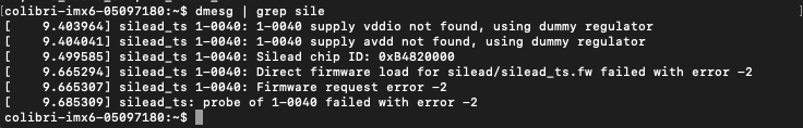
After setting the file in the correct path, I am now getting the following error:
[upload|+h4Y83ydMNqkkw2RAZsZuH8yRiQ=]
which is located in line 306.
So, firmware is not loading.
I went back to make sure that the chip was there with i2cdetect and indeed I see it:
[upload|3pR7tZ6K1HEs3jsugaUyAlbl6I0=]
What’s more, judging by the Silead chip .... line, i2c bus does read from the chip. The problem lies in writing to the chip. From what I can understand, the error is caused because the registers in the chip are not written correctly. Wouldn’t you agree?
Yes -110 means “Connection timed out”.
The i2c_smbus_write_i2c_block_data are trying to communicate and send firmware data without success.
which of these firmwares are you using?
@matheus.tx I am using this one: gsl-firmware/firmware/eastrising/er-tpc050-1 at master · onitake/gsl-firmware · GitHub